
User guide


Operation
PRBS Generator 10 Gb/s User Guide 25
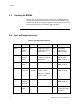
Connector Description DC Level DC Level Z0 Notes
M1 – M3
Mark/space
select
N/A N/A N/A
Selected by closure
to lower pin. Refer
to Figure 6.
Reset Reset PRBS N/A N/A N/A
Selected by closure
to lower pin. Refer
to Figure 6.
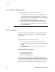
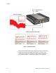
The turning of the cable or connector while connecting the coupling nut of
the connector turns the center contacts while they are engaging. This wears
the plating, thereby decreasing the signal integrity and operating life of the
connectors. Hold the body of the connector while using a torque wrench to
loosen the coupling nut.
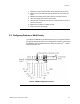
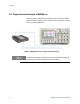
4.5 System Verification
Figure 7 shows a configuration used to verify the performance of the PRBS
source with an external clock. The N4970A internal clock can also be used,
with the CLK/16 output triggering a sampling oscilloscope.
This verification confirms the operation of five pattern lengths, mark density,
and waveshape characteristics.