
User`s guide
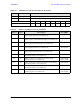
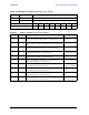
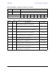
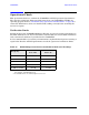
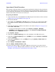
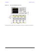
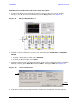

Table Of Contents
- U3042AE12
- Title Page
- TOC
- Introduction
- Description
- Available Options
- Verifying the Shipment
- General Specifications
- Typical Reflection Tracking
- Front and Rear Panel Features
- System Setup with N5230A/C
- Controlling the Test Set with N5230A
- System Setup with N5242A
- Controlling the Test Set with N5242A or N5230C
- DUT Control Lines
- Test Set I/O Interface Commands
- Operational Check
- Troubleshooting Operational Check Failures
- Service Information
- Theory of Operation
- RF Switch Components
- S100 - Source to Ports (1, 5, 9 and 13)
- S200 - Source to Ports (2, 6, 10 and 14)
- S300 - Source to Ports (3, 7, 11 and 15)
- S400 - Source to Ports (4, 8, 12 and 16)
- S101 - Receiver to Ports (1, 5, 9 and 13)
- S201 - Receiver to Ports (2, 6, 10 and 14)
- S301 - Receiver to Ports (3, 7, 11 and 15)
- S401 - Receiver to Ports (4, 8, 12 and 16)
- RF Coupler Components
- System Block Diagram
- Safety and Regulatory Information
- Electrostatic Discharge Protection
- Contacting Agilent
User’s Guide 71
U3042AE12 Operational Check
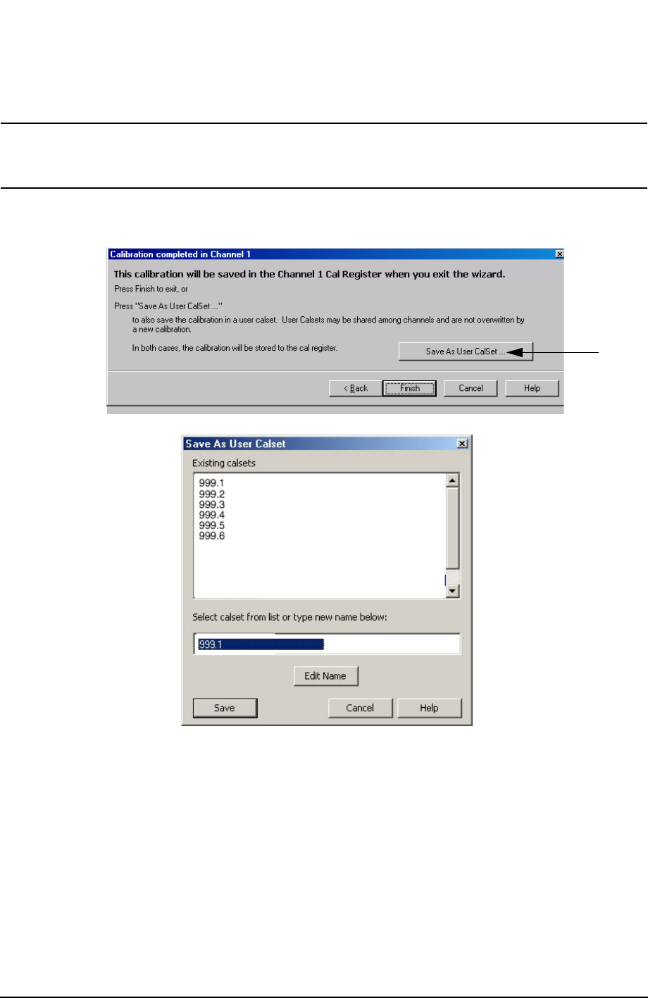
5. At the Calibration Completed prompt, select Save As User Calset and type the name
999.1. Overwrite the Calset if it already exists. Press Save.
NOTE If you do not have a key board, select Save As User Calset > Edit Name and
save as 999.x. X is the port number you are calibrating. See Figure 53. Use
the numeric keypad on the PNA front panel to enter "999.1."
Figure 53 Calibration Complete
6. Repeat step 1 thru step 5 (1-Port Calibration Procedure) for Ports 2 thru 16. When
finished, there should be sixteen Cal Sets saved with the titles “999.1” thru “999.16”
(16-Port).
If you are using an ECal module you can verify the individual port calibration by
selecting Calibration > ECal Confidence Check. For further information refer to the
system Help menu.
7. Press Trace > Delete Trace. There should be no traces on the PNA screen.