
User`s guide
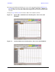
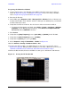
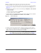
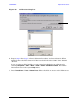
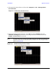

Table Of Contents
- U3042AE12
- Title Page
- TOC
- Introduction
- Description
- Available Options
- Verifying the Shipment
- General Specifications
- Typical Reflection Tracking
- Front and Rear Panel Features
- System Setup with N5230A/C
- Controlling the Test Set with N5230A
- System Setup with N5242A
- Controlling the Test Set with N5242A or N5230C
- DUT Control Lines
- Test Set I/O Interface Commands
- Operational Check
- Troubleshooting Operational Check Failures
- Service Information
- Theory of Operation
- RF Switch Components
- S100 - Source to Ports (1, 5, 9 and 13)
- S200 - Source to Ports (2, 6, 10 and 14)
- S300 - Source to Ports (3, 7, 11 and 15)
- S400 - Source to Ports (4, 8, 12 and 16)
- S101 - Receiver to Ports (1, 5, 9 and 13)
- S201 - Receiver to Ports (2, 6, 10 and 14)
- S301 - Receiver to Ports (3, 7, 11 and 15)
- S401 - Receiver to Ports (4, 8, 12 and 16)
- RF Coupler Components
- System Block Diagram
- Safety and Regulatory Information
- Electrostatic Discharge Protection
- Contacting Agilent
74 User’s Guide
U3042AE12 Operational Check
Preparing the N5242A or N5230C
1. Connect the Test Set to the N5242A 4-Port PNA-X using the interconnect cables as
shown in Figure 29 on page 39 and Table 11 on page 38. If you are using a N5230C,
refer to Figure 50 on page 69 and Table 10 on page 16.
2. Turn On the Test Set.
3. On the PNA, press Response > CAL > Manage CALS > CAL Set. Delete or Rename any
Cal Sets titled “999.1” thru “999.16” (16-Port), although it is unlikely that you will find
Cal Sets with these names.
4. Verify that the PNA is in 16-Port. See the bottom of the measurement window.
a. If only four S-Parameters are listed, press Utility > System > Configure > Multiport
Capability. On the Multiport Restart dialog, select Restart as multiport PNA with
this test set. Select U3042AE12 (16-Port).
5. Press Preset.
6. Verify that the [Stop Frequency] is set to [26.5 GHz], or [20 GHz] for the N5230C.
7. Verify that the [Start Frequency] is set to [10 MHz].
8. Verify that the [Power] is to set to [−5 dBm].
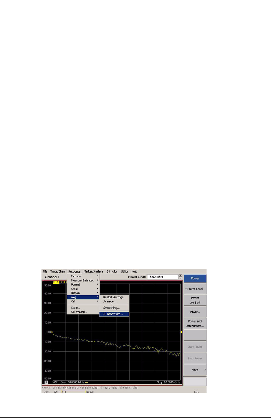
9. Select Response > Avg > IF Bandwidth > 100 Hz. See Figure 58.
10.Select Stimulus > Sweep > Number of Points > 401.
11.Connect the ECal module to the PNA USB port on the front or rear panel, refer to
Figure 50 on page 69. This procedure assumes you are using a ECal. If you are not, see
“N5242A or N5230C 1-Port Calibration and Verification Procedure” step 2.
12.Allow the ECal module, Test Set and PNA to warm up for a minimum of 30 minutes.
Figure 58 Setting the IF Bandwidth