
User`s guide
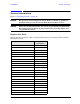
Table Of Contents
- U3042AE12
- Title Page
- TOC
- Introduction
- Description
- Available Options
- Verifying the Shipment
- General Specifications
- Typical Reflection Tracking
- Front and Rear Panel Features
- System Setup with N5230A/C
- Controlling the Test Set with N5230A
- System Setup with N5242A
- Controlling the Test Set with N5242A or N5230C
- DUT Control Lines
- Test Set I/O Interface Commands
- Operational Check
- Troubleshooting Operational Check Failures
- Service Information
- Theory of Operation
- RF Switch Components
- S100 - Source to Ports (1, 5, 9 and 13)
- S200 - Source to Ports (2, 6, 10 and 14)
- S300 - Source to Ports (3, 7, 11 and 15)
- S400 - Source to Ports (4, 8, 12 and 16)
- S101 - Receiver to Ports (1, 5, 9 and 13)
- S201 - Receiver to Ports (2, 6, 10 and 14)
- S301 - Receiver to Ports (3, 7, 11 and 15)
- S401 - Receiver to Ports (4, 8, 12 and 16)
- RF Coupler Components
- System Block Diagram
- Safety and Regulatory Information
- Electrostatic Discharge Protection
- Contacting Agilent

80 User’s Guide
U3042AE12 Troubleshooting Operational Check Failures
Troubleshooting Operational Check Failures
If your test results fail the Operational Check limits, verify following:
1. Insure that the test set is turned on and connected properly to the PNA.
2. Check all appropriate network analyzer and test set connectors for damage, cleanliness,
and proper torque.
3. Repeat the relevant 1-Port calibrations.
4. Verify that the stand-alone network analyzer is operating properly and meeting its
published specifications.
Interconnect Cable Verification
1. Connect the Test Set to the PNA and select Multiport mode.
2. Verify the Source Interconnect RF cables (Source Out and CPLR THRU).
a. Remove the Receiver and CPLR ARM interconnect cables and install the standard
PNA jumpers.
b. Connect two RF cables on the PNA, Port-1 to Port-2 and Port-3 to Port-4.
c. Set the PNA to measure Trace S12, S21, S34 and S43, and verify that there are no
power holes. If S12, or S34 has a power hole check the Port-2, or Port-4 Source
interconnect cables and test set connectors for damage. If S21, or S43 has a power
hole check the Port-1, or Port-3 Source interconnect cables and test set connectors for
damage.
3. Verify the Receiver Interconnect RF cables (Receiver A IN or B IN and CPLR ARM).
a. Re-install the Receiver and CPLR ARM interconnect cables.
b. Remove the Source Out and CPLR THRU interconnect cables and install the
standard PNA jumpers.
c. Set the PNA to measure Trace S12, S21, S34 and S43. Verify that there are no power
holes. If S12 or S34 has a power hole check Port-1, or Port-3 Receiver Interconnect
cables and test set connectors for damage. If S21, or S43 has a power hole check
Port-2, or Port-4 Receiver Interconnect cables and test set connectors for damage.
4. If the problem still exists, connect the standard jumpers to the PNA (Source and
Receiver) and verify the Source Out to CPLR THRU and A/B IN to CPLR ARM switch
paths.
a. Connect two RF cable, one to Port-1 and one to Port-2.
b. Set the PNA to measure trace S12 (all standard jumpers connected).
c. Connect the Port-1 cable to Source Out and Port-2 cable to CPLR THRU connectors
on the test set. If a power hole still exists refer to “Contacting Agilent” on page 94.
d. Connect Port-1 to Receiver A IN or B IN and Port-2 to CPLR ARM connectors on the
test set. If a power hole still exists refer to “Contacting Agilent”.