
User`s guide

User’s Guide U3025-90001 15
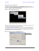
U3025AE10 System Setup E8363C, E8364C or N5230C
RF Interface Cable Connections
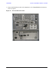
Figure 10 illustrates the setup configuration of the U3025AE10 Multiport Test Set and
how it should be configured to the E8364C 2-Port and N5230C PNA Network Analyzer.
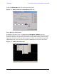
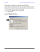
1. Remove the SOURCE OUT to CPLR THRU and RCVR IN to CPLR ARM jumpers (x8)
on the PNA. The RCVR R1 - R2 to SOURCE OUT reference loop jumpers (x2) remain on
the front panel.
2. Connect the RF cables supplied with this option between the network analyzer and the
U3025AE10 Test Set. Torque each cable to 8 in-lb. Refer to Table 5 and Figure 10 on
page 15.
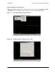
CAUTION Each end of the interconnect RF cables have a different length from the bend.
When connecting the RF Interconnect cables be sure that the longer end from
the bend is connected to the PNA.
CAUTION Over torque will cause damage to the Test Set and may cause connectors to
spin or become loose.
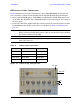
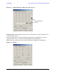
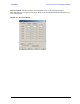
Figure 10 12-Port Setup Configuration
Table 5 12-Port Cable Connection
RF Cables From (PNA) To (Test Set)
U3025-20044 SOURCE OUT SOURCE OUT
U3025-20044 CPLR THRU CPLR THRU
U3025-20045 CPLR ARM CPLR ARM
U3025-20045 RCVR A IN, B IN A IN, B IN
44 (x4)
45
44
45 (x4)