
Technical data

Service Guide N5230-90025 4-33
PNA Series Microwave Network Analyzers Troubleshooting
N5230C Measurement System Troubleshooting
Checking the A7 Fractional-N Synthesizer Output, Bands 5 through 17
Perform this procedure if you observe a problem in bands 5 through 17 in all receivers.
1. Set the network analyzer to measure a CW frequency of 2 GHz.
• The spectrum analyzer should measure a signal at 2 GHz (plus the 7.66 MHz offset).
2. If the signal is not present, replace the A7 fractional-N synthesizer board. Refer to “Removing and
Replacing the A5 through A10 Boards” on page 7-16.
3. If the signal is present, reconnect cable W1, and then continue with “Checking the A6 Multiplier Output,
All Bands” on page 4-34.
* Applies to 13.5 GHz analyzers only.
** Applies to 20 GHz analyzers only.
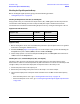
Table 4-4 LO Path Frequencies
Options Band
Network Analyzer
Frequency Band
of Problem
(GHz)
Network Analyzer
Source Frequency
Setting
(GHz)
Expected A7
Output
Frequency
(GHz)
Expected A6
Output
Frequency
(GHz)
140,
145,
146,
240,
245,
or
246
0 0.0003 to 0.001 0.0007 0.00836 0.00836
1 0.001 to 0.010 0.005 0.01266 0.01266
2 0.010 to 0.040 0.025 0.03266 0.03266
3 0.040 to 0.748 0.060 0.06766 0.06766
4 0.748 to 1.500 1.100 1.10766 1.10766
5 1.500 to 3.125 2.200 2.20766 2.20766
6 3.125 to 4.167 3.600 1.80383 3.60766
7 4.167 to 5.250 4.600 2.30383 4.60766
8 5.250 to 6.250 5.700 2.85383 5.70766
9 6.250 to 8.333 6.700 1.67692 6.70766
10 8.333 to 9.800 9.000 2.25192 9.00766
11 9.800 to 10.500 10.200 2.55192 10.20766
12 10.500 to 12.500 11.500 1.91794 3.83588
13* 12.500 to 13.500 13.000 2.17050 4.34099
240,
245,
or
246
13** 12.500 to 15.000 13.700 2.28461 4.56922
14 15.000 to 15.750 15.400 2.56794 5.13588
15 15.750 to 16.667 16.200 2.70128 5.40255
16 16.667 to 18.750 17.700 2.95128 5.90255
17 18.750 to 20.000 19.300 1.60897 6.43588