
Technical data

Service Guide N5230-90025 5-9
PNA Series Microwave Network Analyzers Theory of Operation
N5230C Synthesized Source Group Operation
Frequency Offset Operation (Option 080)
Since the A7, A9 and A13 fractional-N synthesizer boards each contain their own phase lock circuitry, they
can be phase locked independently to different output frequencies. Normally the LO signal is automatically
tuned to a frequency 7.66 MHz higher than that of the test signal to create the 7.66 MHz difference
frequency (IF) in the A20 mixer brick.
In frequency offset mode (Option 080), the LO signal can be independently tuned to any frequency (within its
tuning range) to allow for frequency offset measurements needed when testing devices such as mixers and
converters.
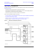
A7, A9, and A13 (Options 146 and 246) Fractional-N Synthesizer Boards
The A7, A9, and A13 fractional-N synthesizer boards use the 5 MHz reference signal from the A10 frequency
reference board to tune two VCO circuits: one that sweeps from 1500 to 3125 MHz and one that is set to a
CW frequency of 2250 MHz.
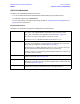
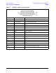
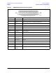
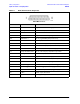
In bands 0–3, these signals are mixed to produce the output frequencies listed in Ta b l e 5 - 2 . In band 4, the
output of the swept VCO is passed through a divide-by-2 circuit to produce the output frequencies listed in
Ta b l e 5 - 2 . In all other bands, the swept VCO signal is sent directly to the synthesizer output.
At the output, an ALC circuit maintains the power level at -5 dBm for bands 0–3 or
dBm for bands 4–17. In all
bands, the output is sent to either the A6, A8, or A12 multiplier board.
The output of the A7 fractional-N synthesizer board is 7.66 MHz higher than the output of the A9 and A13
fractional-N synthesizer boards. This is because the output of the A7 fractional-N synthesizer board is
routed through the A6 multiplier board to the A20 mixer brick where it is mixed with the test signal to
produce a 7.66 MHz IF signal for each of five channels. Refer to “A20 Mixer Brick” on page 5-22 for a more
complete description.
A6, A8, and A12 (Options 146 and 246) Multiplier Boards
In bands 0–5, the input signal from the A7 A9, or A13 fractional-N synthesizer board is passed through the
multiplier board unchanged. For all other bands, the signals are doubled, filtered, and amplified. In the A6
board, in bands 9–11 and 17, the signals are again doubled, filtered, and amplified. In the A8 and A12 boards,
in bands 9– 11 and 13–17, the signals are again doubled, filtered, and amplified. Together these signals
create the full output frequency range of 300 kHz to 10.508 GHz for the A6 board or 300 kHz to 10.5 GHz for
the A8 and A12 boards.
A19 and A18 (Options 146 and 246) Multiplier/Amplifier/Switch/Splitter 26.5 (MASS
26.5) (MASSQuad)
In bands 0–11, the 300 kHz to 10.5 GHz inputs are filtered, amplified, and passed through the MASSQuad. In
bands 12–17, they are doubled, filtered, and amplified.
Together, these signal paths create the full output frequency range of 300 kHz to 20 GHz that is sent to the
splitter where a portion of the signal is used for the R channel reference signal and another portion for the
ALC circuit on either the A16 test set motherboard (for the A19) or the A17 QABC board (for the A18).