
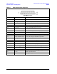
Technical data
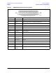

Service Guide N5230-90025 5-17
PNA Series Microwave Network Analyzers Theory of Operation
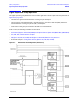
N5230C Signal Separation Group Operation
A19 and A18 (Options 146 and 246) Multiplier/Amplifier/Switch/Splitter 26.5 (MASS
26.5) (MASSQuad)
After the source signal has been amplified, filtered, and multiplied, it is sent to the splitter where a portion of
the signal is split off to provide the R channel reference signal.
Options 146 and 246 include a reference channel switch (A29), a limiter, and a DC block in the reference
channel path to provide the capability to select either source 1 or source 2 as the reference signal. See “A 29
Reference Channel Switch, Limiter, and DC Block (Options 146 and 246)” on page 5-22 for additional
information.
Another portion of the source signal is split off and sent to the ALC circuitry, (located on the A16 test set
motherboard for the A19 and on the A17 QABC board for the A18), to provide leveling control.
The remaining signal is sent to a switch (through a step attenuator for Options 145, 146, 245, and 246) where
it is switched to the test port couplers.
• For Options 145 and 245, the signal from the A19 MASSQuad is sent through the A25 source step
attenuator back to a switch on the A19 MASSQuad where it is switched to one of the four test port
couplers, A21–A24.
• For Options 146 and 246, the signal from the A19 source 1 MASSQuad is sent through the A25 source
step attenuator back to a switch on the A19 MASSQuad where it is switched to either the A21 or A22
test port coupler.
The signal from the A18 source 2 MASSQuad is sent through the A26 source step attenuator back to a
switch on the A18 MASSQuad where it switched to either the A23 or A24 test port coupler.
Refer also to “A19 and A18 (Options 146 and 246) Multiplier/Amplifier/Switch/Splitter 26.5 (MASS 26.5)
(MASSQuad)” on page 5-9.
A21, A22, A23, and A24 Test Port Couplers
The test port signal goes into the through-line arm of the couplers, and from there to the test ports and the
DUT. The coupled arm of the couplers carries the signal reflected from or transmitted through the DUT, to the
receiver (through a front panel jumper for Options 146, 146, 245 and 246) for measurement. The coupling
coefficient of the directional couplers is nominally 15 dB over the full frequency range.
A25 (Options 145, 245, 146, and 246) and A26 (Options 146 and 246) 60-dB Source Step
Attenuator
The 60-dB step attenuator provides coarse power control for the test port signals. It is an
electro-mechanical step attenuator that provides 0 to 60 dB of attenuation in 10-dB steps. It adjusts the
power level to the DUT without changing the level of the incident power in the reference path. This
attenuator is controlled by the A15 CPU board.