
Technical data

7-22 Service Guide N5230-90025
Repair and Replacement Procedures PNA Series Microwave Network Analyzers
Removing and Replacing the A14 System Motherboard N5230C
Removing and Replacing the A14 System Motherboard
Tools Required
• T-10 TORX driver (set to 9 in-lb)
• T-20 TORX driver (set to 21 in-lb)
• 5/16 inch open-end torque wrench (set to 10 in-lb)
• ESD grounding wrist strap
Removal Procedure
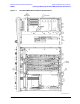
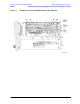
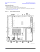
Refer to Figure 7-9 for this procedure.
1. Disconnect the power cord.
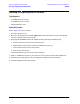
2. Remove the outer and inner covers. Refer to “Removing the Covers” on page 7-6.
3. Remove the front panel assembly. Refer to “Removing and Replacing the Front Panel Assembly” on
page 7-8.
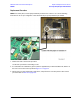
4. Remove the A4 power supply assembly. Refer to “Removing and Replacing the A4 Power Supply
Assembly” on page 7-14.
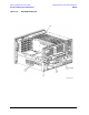
5. Remove the A5 through A10 boards and the plenum bracket. Refer to “Removing and Replacing the A5
through A10 Boards” on page 7-16.
6. Remove the A12 multiplier and A13 fractional-N synthesizer boards. Refer to “Removing and Replacing
the A12 Multiplier and the A13 Fractional-N Synthesizer Boards” on page 7-20.
7. Remove the A17 QABC board. Refer to “Removing and Replacing the A17 QABC Board” on page 7-30.
8. Remove the A11 vertical motherboard. Refer to “Removing and Replacing the A11 Vertical Motherboard
and the Plenum Bracket” on page 7-18.
9. Remove the A15 CPU board. Refer to “Removing and Replacing the A15 CPU Board” on page 7-24.
10. Remove the Midweb. Refer to “Removing and Replacing the Midweb and the B1 Fan” on page 7-53.
11. Remove the ribbon cable clamp (item
⑧
) by removing the attachment screw (item
⑨
). Set the cable
clamp aside for reinstallation later.
12. Disconnect the front panel ribbon cable (item
①
), the USB hub assembly cable (item ➁), and the test
set motherboard ribbon cable (item
③
) from the A14 system motherboard.
13. Remove the remaining three screws (item
④
) that secure the A14 system motherboard.
14. Remove the power switch push button (item
⑤
) and spring (item
⑥
).
15. Slide the A14 system motherboard toward the front of the analyzer to release the hold-down pins (item
⑦
) and lift the motherboard out of the analyzer.