
Technical data

7-40 Service Guide N5230-90025
Repair and Replacement Procedures PNA Series Microwave Network Analyzers
Removing and Replacing the A25 60-dB Source Step Attenuator N5230C
Removing and Replacing the A25 60-dB Source Step Attenuator
Tools Required
• T-10 TORX driver (set to 9 in-lb)
• T-20 TORX driver (set to 21 in-lb)
• 5/16-inch open-end torque wrench (set to 10 in-lb)
• ESD grounding wrist strap
Removal Procedure
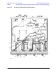
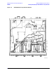
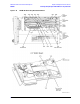
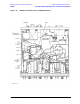
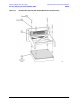
Refer to Figure 7-17 for this procedure.
1. Disconnect the power cord.
2. Remove the outer cover. Refer to “Removing the Covers” on page 7-6. Position the analyzer bottom side
up.
3. Disconnect the ribbon cable (item
①
) from the A25 step attenuator.
4. Using a 5/16-inch wrench, disconnect the semi-rigid cables (item
➁) from the A25 step attenuator.
5. With a T-10 TORX driver, loosen the mounting screws (item
③
) in the analyzer side frame. It is not
necessary to completely remove the mounting screws.
CAUTION Be careful not to damage the center pins of the semirigid cables. Some flexing of the cables
is necessary to remove the assembly. Do not over bend them.
6. Slide the attenuator upward to release the mounting screws and remove the A25 step attenuator from
the analyzer. Observe the
CAUTION above.
Replacement Procedure
1. Remove the mounting screws from the old attenuator and insert them loosely into the new attenuator.
2. Reverse the order of the removal procedure.
Use the tools specified for all cable connections and mounting screws.
3. Perform the post-repair adjustments, verifications, and performance tests that pertain to this removal
procedure. Refer to Table 7-2 on page 7-58.