
Technical data

Service Guide N5230-90025 4-21
PNA Series Microwave Network Analyzers Troubleshooting
N5230C Rear Panel Troubleshooting
Tes ting B etw ee n Two Anal yze rs
The ability of the analyzer's LAN to function can be easily tested by connecting two analyzers together using
a “crossover cable” (a short length of cable with an RJ-45 connector on each end).
Some network hubs have the capability to make a crossover connection using two normal, or
straight-through, cables. If this capability is not available and a crossover cable is not available, a crossover
cable can be made by following the directions in “Constructing a Crossover Cable” on page 4-21.
Set the IP addresses on two analyzers. The addresses can be set to anything, but they must be different.
Make sure the subnet mask and gateway addresses are set to 0.0.0.0 and that the LAN is active on both
analyzers. Connect the two analyzers together using either a crossover cable or a crossover hub.
Now follow the steps in “How to Ping from the Analyzer to the Local Area Network (LAN)” on page 4-19 to
have the first analyzer ping the second analyzer. When done, repeat the procedure having the second
analyzer ping the first. If both procedures function properly, the LAN circuitry on both analyzers is verified.
If neither function properly:
• One or both IP addresses could be wrong.
• One or both LAN states could be set to off.
• The crossover cable could be miswired.
• One or both analyzers could be defective.
If possible, eliminate the possibility of a defective analyzer by substitution of a known working unit. Once the
analyzer has been proven to be working properly, concentration can be placed on the network itself to
determine the cause of the failure.
Constructing a Crossover Cable
A crossover cable can be made from a standard LAN cable by connecting pin 1 from each connector to pin 3
of the other connector, and pin 2 from each connector to pin 6 of the other connector.
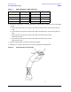
1. Strip away a few inches of the outside jacket insulation from the middle of a standard LAN cable that has
an RJ-45 connector on each end.
NOTE Pins 1, 2, 3, and 6 of the connectors must be located to determine which wires to cut in the
following steps. Most, but not all, LAN cables use the color coding listed in Ta bl e 4 - 3 . If your
cable does not use this color scheme, you will have to determine the locations of the
appropriate wires before proceeding with this procedure.