
Technical data

Low and Full Speed Tests 7
Notes on USB Electrical Compliance Testing 187
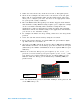
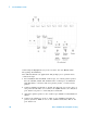
5 Connect the Channel 2 probe to the Vbus test point on the load board
connected adjacent to the USB port to be measured. This provides the
oscilloscope trigger.
6 Check I have completed these instructions.
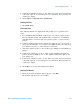
Running the Tests
1 Click Run Tests.
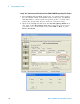
Test Instructions
The USB automated test application will prompt you to perform these
steps:
1 For 54831B/D and 54832B/D oscilloscopes, use 1165A passive probes.
For the 5485XA, 80000 and 90000A Series oscilloscpes, use E2697A
high- impedance converter with 10:1 passive probes, or 1156A active
probes.
2 Connect 500 mA load boards to all but the adjacent port on the host or
self- powered hub under test. Connect the SQiDD board to the hub/host
port under test prior to connecting the load board .
3 Attach the passive probes to the oscilloscope's Channel 1 and Channel 2
inputs.
4 Connect the Channel 1 probe to Vbus on the SQiDD board with the
probe's ground to GND on one of the 500mA load boards. This is the
port under test.
5 Connect the Channel 2 probe to the Vbus test point on the load board
connected adjacent to the USB port to be measured. This provides the
oscilloscope trigger.
6 Click OK to close the Test Instructions dialog.
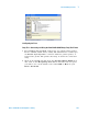
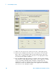
Viewing Test Results
1 When the Testing Complete dialog appears, click OK.
The Results tab shows the test results.