Agilent N8201A Performance Downconverter Synthetic Instrument Module, 3 Hz to 26.
Notices © Agilent Technologies, Inc. 2006 - 2008 Manual Part Number No part of this manual may be reproduced in any form or by any means (including electronic storage and retrieval or translation into a foreign language) without prior agreement and written consent from Agilent Technologies, Inc. as governed by United States and international copyright laws. N8201-90006 Edition Edition, January 22, 2008 Printed in USA Windows® Agilent Technologies, Inc.
Introducing the N8201A Performance Downconverter The Agilent Technologies N8201A performance downconverter down converts a microwave signal to an IF signal providing IF output frequencies of 7.5, 21.4, and 321.4 MHz to offer three different signal bandwidth capabilities. External mixing can be utilized to down convert microwave signals up to 110 GHz. The N8201A is based upon the industry’s most accurate spectrum analyzer, the PSA Series.
Agilent N8201A Performance Downconverter Synthetic Instrument Module, 3 Hz to 26.
Contents Introducing the N8201A Performance Downconverter 3 1 Software Installation Installing Software and Instrument Drivers 6 Step 1. Install Microsoft .NET Version 1.1 7 Step 2. Install the Agilent I/O Libraries 8 Step 3. Install the IVI Shared Components 9 Step 4. Install the Agilent Synthetic Instrument Finder 11 Step 5. Install the Agilent Synthetic Instrument GUI 12 Step 6. Install the IVI-COM Drivers 13 Step 7.
How to Determine a PCs Configuration Settings 60 If the Instrument was Unable to Join the LAN 62 If the LAN LED is Red 62 If the Instrument’s IP Address or Hostname Cannot be Found with Ping If the Instrument is Not Found by the Synthetic Instrument Finder 63 If the Instrument’s Hostname and PC Cannot Communicate 63 If the Instrument Web Page is Not Visible 64 If the Software Driver Will Not Open the Connection 64 63 3 Using the Agilent Synthetic Instrument GUI Starting the Agilent Synthetic Instrument GU
COHERENT CARRIERS 84 EXT MIXER 85 IF OUTPUTS 85 TRIGGERS 85 REFERENCES 85 IF LOG VIDEO (Option V7L) 86 NOISE SOURCE +28 V (PULSED) (Option 219) VGA OUT 86 86 N8201A Performance Downconverter Rear Panel Features AC Power Receptacle 87 LAN 87 LXI Trigger Bus 88 Interconnect Cabling 87 89 Operational Considerations 90 Agilent 89601A Vector Signal Analysis Software 90 Configuring the Local Area Network (LAN) Interface 90 5 Preventive Maintenance Using, Inspecting, and Cleaning RF Connectors Repeatability
Safety 104 Safety Summary 104 Equipment Installation 105 Environmental Conditions 106 Before Applying Power 106 Magnetic Susceptibility 107 Vibration 107 Ground the Instrument or System 107 Fuses and Circuit Breakers 108 Maintenance 108 Safety symbols and Instrument Markings 108 Service and Support 111 Agilent on the Web 111 Return Procedure 112 Shipping the Instrument 112 7 Glossary 4 Agilent N8201A Performance Downconverter Synthetic Instrument Module, 3 Hz to 26.
User’s Guide 1 Software Installation This installation process installs the required software and instrument drivers used by the N8201A performance downconverter: “Verify the PC Meets Minimum Requirements" on page 6 “Step 1. Install Microsoft .NET Version 1.1" on page 7 “Step 2. Install the Agilent I/O Libraries" on page 8 “Step 3. Install the IVI Shared Components" on page 9 “Step 4. Install the Agilent Synthetic Instrument Finder" on page 11 “Step 5.
1 Software Installation Installing Software and Instrument Drivers 1 Verify the PC Meets Minimum Requirements • 1 GHz Intel Pentium processor • Microsoft Windows XP Professional or Home Edition (Service Pack 1 or 2), Windows 2000 (Service Pack 2) • 512 MB of RAM • Up to 40 MB of available hard- disk space • Microsoft Internet Explorer 6.0 (or higher), or Netscape 7.1 or 8.0 2 Place the CD with the Instrument Drivers and Documentation in the CD-ROM drive. NO TE a Adobe Acrobat Reader 5.
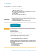
Software Installation 1 Step 1. Install Microsoft .NET Version 1.1 1 Select Microsoft Version 1.1. 2 Click the check box, “Do not show this message again” so that the check box is selected. This will stop the message from displaying each time a selection is made from the Software and Driver Installation menu. 3 Click Open. 4 Follow the installation instructions and accept the default settings. 5 Click Finish. Agilent N8201A Performance Downconverter Synthetic Instrument Module, 3 Hz to 26.
1 Software Installation Step 2. Install the Agilent I/O Libraries 1 Select Agilent I/O Libraries. 2 Follow the instructions and accept the default settings. 3 Click Finish. 8 Agilent N8201A Performance Downconverter Synthetic Instrument Module, 3 Hz to 26.
Software Installation 1 Step 3. Install the IVI Shared Components 1 Select IVI Shared Components. 2 Run the IviCleanupUtility before running the IviSharedComponents or a network access error may occur during installation of the IviSharedComponents. Agilent N8201A Performance Downconverter Synthetic Instrument Module, 3 Hz to 26.
1 Software Installation 3 Follow the installation instructions and accept the default settings. 4 Click Finish. 10 Agilent N8201A Performance Downconverter Synthetic Instrument Module, 3 Hz to 26.
Software Installation 1 Step 4. Install the Agilent Synthetic Instrument Finder 1 Select Agilent Synthetic Instrument Finder. 2 Follow the installation instructions and accept the default settings. 3 Click Close. Agilent N8201A Performance Downconverter Synthetic Instrument Module, 3 Hz to 26.
1 Software Installation Step 5. Install the Agilent Synthetic Instrument GUI 1 Select Agilent Synthetic Instrument GUI. 2 Follow the installation instructions and accept the default settings. Click Close. 12 Agilent N8201A Performance Downconverter Synthetic Instrument Module, 3 Hz to 26.
Software Installation 1 Step 6. Install the IVI-COM Drivers There are two different IVI-COM drivers available for the N8201A performance downconverter. • If the N8201A performance downconverter is equipped with Option H02, a different IVI-COM driver is available that enables functionality similar to a PSA spectrum analyzer. • If the N8201A performance downconverter is not equipped with Option H02, only downconverter functions are available. 1 Select one of the IVI-COM Drivers.
1 Software Installation 2 Follow the installation instructions and accept the default settings. You should see the above dialog when the installation is complete for IVI-COM that supports Option H02 and the below dialog when the installation is complete for IVI-COM that supports N8201A performance downconverters that are not equipped with Option H02. 3 Click Finish. 14 Agilent N8201A Performance Downconverter Synthetic Instrument Module, 3 Hz to 26.
Software Installation 1 Step 7. Install the Agilent N8201A Performance Downconverter User Interface 1 Select Agilent N8201A Performance Downconverter User Interface. 2 Follow the installation instructions and accept the default settings. 3 Click Close. Agilent N8201A Performance Downconverter Synthetic Instrument Module, 3 Hz to 26.
1 Software Installation Installing Optional Software and Instrument Drivers Software for steps 8, 9, 10, and 11 can be installed on your PC, but Option H02 is required to use these software applications with the N8201A performance downconverter; prior to continuing, verify that Option H02 is installed. To Verify that Option H02 is Installed 1 Start the Synthetic Instrument Finder (from the Windows Desktop, click Start > All Programs > Agilent SI Tools > Synthetic Instrument Finder).
Software Installation 1 (Optional) Step 8. Install the Agilent N8201A Option H02 Spectrum Analyzer GUI NO TE Before performing this optional installation step, read about “Installing Optional Software and Instrument Drivers" on page 16. 1 Select Agilent N8201A Option H02 Spectrum Analyzer GUI. Agilent N8201A Performance Downconverter Synthetic Instrument Module, 3 Hz to 26.
1 Software Installation 2 Follow the installation instructions and accept the default settings. 3 Click Close. 18 Agilent N8201A Performance Downconverter Synthetic Instrument Module, 3 Hz to 26.
Software Installation 1 (Optional) Step 9. Install the Microsoft Virtual Machine (VM) NO TE Before performing this optional installation step, read about “Installing Optional Software and Instrument Drivers" on page 16. 1 Select Microsoft Virtual Machine (VM). 2 Follow the installation instructions and accept the default settings. 3 Click OK. Agilent N8201A Performance Downconverter Synthetic Instrument Module, 3 Hz to 26.
1 Software Installation 4 Click No on the Microsoft VM dialog box. This step will be completed later in the process after the SA Remote Web Server is installed. 20 Agilent N8201A Performance Downconverter Synthetic Instrument Module, 3 Hz to 26.
Software Installation 1 (Optional) Step 10. Install the Apache HTTP Server NO TE Before performing this optional installation step, read about “Installing Optional Software and Instrument Drivers" on page 16. 1 Select Apache HTTP Server. Agilent N8201A Performance Downconverter Synthetic Instrument Module, 3 Hz to 26.
1 Software Installation 2 Follow the installation instructions and accept the default settings 3 Click Next. 4 Click Next. 22 Agilent N8201A Performance Downconverter Synthetic Instrument Module, 3 Hz to 26.
Software Installation 1 5 Click Finish. Agilent N8201A Performance Downconverter Synthetic Instrument Module, 3 Hz to 26.
1 Software Installation (Optional) Step 11. Install the SA Remote Web Server NO TE Before performing this optional installation step, read about “Installing Optional Software and Instrument Drivers" on page 16. 1 Select SA Remote Web Server. 24 Agilent N8201A Performance Downconverter Synthetic Instrument Module, 3 Hz to 26.
Software Installation 1 2 Follow the installation instructions and accept the default settings. 3 Click Finish. 4 Click Cancel on the Configure dialog box. This step will be completed later in the process after restarting the computer. 5 Close the Agilent N8201A Performance Downconverter Software and Driver Installation menu (driver_installation_list.pdf dialog box). 6 Click Exit CD-ROM. The software and driver installation is complete.
1 26 Software Installation Agilent N8201A Performance Downconverter Synthetic Instrument Module, 3 Hz to 26.
User’s Guide 2 Hardware Setup and Configuration “Step 1. Unpack the N8201A Performance Downconverter" on page 28 “Step 2. Connect LAN Cables and Turn On Power" on page 29 “Step 3. Verify Connection with Synthetic Instrument Finder" on page 32 “(Optional) Step 4. Connect to the Agilent N8201A Option H02 Spectrum Analyzer GUI" on page 34 “(Optional) Step 5. Connect to an SA Remote Web Server" on page 36 “(Optional) Step 6. Verify Operation < 3 GHz" on page 43 “(Optional) Step 7.
2 Hardware Setup and Configuration Step 1. Unpack the N8201A Performance Downconverter WA RN ING NO TE The unique shape of the N8201A performance downconverter was intended to allow multiple instruments to reside in a compact system that is both modular and transportable. With instruments adjacent to each other, handles could not be installed on the respective instruments. Exercise caution when lifting and carrying the instrument to avoid personal injury. At 25.
Hardware Setup and Configuration 2 Step 2. Connect LAN Cables and Turn On Power Install the N8201A performance downconverter so that the detachable power cord is readily identifiable and is easily reached by the operator. The detachable power cord is the instrument disconnecting device. It disconnects the mains circuits from the mains supply before other parts of the instrument. The front panel switch is only a standby switch and is not a LINE switch.
2 Hardware Setup and Configuration 1 Connect a LAN cable from the LAN connector on your PC to an empty connector on your internal local area network or LAN hub. 2 Connect a LAN cable from the LAN connector on the rear panel of the N8201A performance downconverter to an empty connector on your internal local area network or LAN hub. 3 Turn on power to the PC.
2 Hardware Setup and Configuration (Optional) Connect to a LAN with a Cross-Over LAN Cable If you wish to communicate directly between the N8201A performance downconverter and your PC without the use of a LAN hub, you can connect directly to your PC. 1 Connect a cross-over LAN cable from the LAN connector on your PC to the LAN connector on the rear panel of the N8201A performance downconverter. 2 Turn on power to the PC.
2 Hardware Setup and Configuration Step 3. Verify Connection with Synthetic Instrument Finder Agilent supplies a program named the Synthetic Instrument Finder that enables connection between a PC and instruments that are connected on a LAN [Local Area Network]. 1 From the Windows Desktop, click Start > All Programs > Agilent SI Tools > Synthetic Instrument Finder. The Synthetic Instrument Finder should appear and look similar to the following.
Hardware Setup and Configuration 2 3 Select Open Webpage and a Web browser should appear that allows viewing and modifying settings for instruments on the network. • If this Web page does not open or you experience an error, refer to “Troubleshooting" on page 50.
2 Hardware Setup and Configuration (Optional) Step 4. Connect to the Agilent N8201A Option H02 Spectrum Analyzer GUI NO TE If Option H02 is not installed, the Agilent N8201A Option H02 Spectrum Analyzer GUI software cannot be used! In addition to Option H02, you must have performed “(Optional) Step 8. Install the Agilent N8201A Option H02 Spectrum Analyzer GUI" on page 17; this interface can be installed along with the SA Web Remote Server, but only one interface can be used at any given time.
Hardware Setup and Configuration 2 This section describes how to access and use the Agilent N8201A Option H02 Spectrum Analyzer GUI. 1 From the Windows Desktop, click Start > All Programs > Agilent SI Tools > N8201A Option H02 Spectrum Analyzer GUI. 2 Click File > Connect (upper-left corner) on the Agilent N8201A Option H02 Spectrum Analyzer GUI. 3 Enter the VISA Address (for example, TCPIP0::141.121.87.18::inst0::instr) of the instrument being connected to and click OK.
2 Hardware Setup and Configuration (Optional) Step 5. Connect to an SA Remote Web Server NO TE If Option H02 is not installed, the SA Remote Web Server software cannot be used! In addition to Option H02, you must have installed the Microsoft Virtual Machine (VM), the Apache HTTP Server, and the SA Remote Web Server software; this interface can be installed along with the Agilent N8201A Option H02 Spectrum Analyzer GUI, but only one interface can be used at any given time.
Hardware Setup and Configuration 2 3 Select Remote GPIB (via E5810 or Remote IO Server). 4 Click Add. 5 Enter the N8201A performance downconverter’s IP address. If you do not know the IP address, use the Synthetic Instrument Finder. a From the Windows Desktop, select Start > All Programs > Agilent SI Tools> Synthetic Instrument Finder. b Select an instrument from the list of instruments shown to see its IP address.
2 Hardware Setup and Configuration The Remote GPIB interface dialog box should look similar to the following: 6 Select IP address and enter the IP Address of the N8201A performance downconverter in the Remote GPIB Interface dialog box. 7 Enter gpib7 for the Interface Name on Remote Host. 8 Click Test connection. If the connection was successful, text stating “The interface was successfully opened“ should appear. 9 Click OK.
Hardware Setup and Configuration 2 10 From the Windows Desktop, select Start > All Programs > Agilent Web Remote > SA > Configure and a Configure dialog box similar to the following should appear. 11 Click Continue and a dialog box similar to the following should appear. 12 Click Yes on the Instrument Information dialog box. 13 Click OK. 14 From the Windows Desktop, select Start > Run. 15 Enter CMD in the Run dialog box to select the Command Window.
2 Hardware Setup and Configuration 16 From the command window prompt, type ipconfig to get the IP Address of your computer. 17 Write down your computer's IP address. IP Address: __ __ __ . __ __ __ . __ __ __ . __ __ __ This IP address is needed in the following steps. If you are attempting to access the web server from another machine, you need to make sure to use the hostname or IP Address of the adapter that is on the same network as the machine you are using.
Hardware Setup and Configuration 2 18 From the Windows Desktop, select Start > All Programs > Agilent Web Remote > SA > Start Server to start the Spectrum Analyzer Instrument Server. 19 From the Windows Desktop, select Microsoft’s Internet Explorer. 20 Insert your PC’s IP address (from the command window above). Use the following syntax: http://141.121.83.141/index.html and a display similar to the following should appear.
2 Hardware Setup and Configuration 21 Select Web Control SA on the left of the web page. • If one of the following dialog boxes appears, click Run or Install and accept the installation. If the following display appears, the SA Remote Web Server configuration is complete! 42 Agilent N8201A Performance Downconverter Synthetic Instrument Module, 3 Hz to 26.
Hardware Setup and Configuration 2 (Optional) Step 6. Verify Operation < 3 GHz Operation verification is a test that, when completed, will ensure that the downconverter is operating correctly in the low band (< 3 GHz). CAU TI O N Make sure that the total power of all signals at the downconverter input does not exceed +30 dBm (1 watt). Performing a Self-Test Instrument Connections • Downconverter: 7.
2 Hardware Setup and Configuration Perform the following procedure to run a self-test: 1 Close SA Remote Web Server. 2 From the Windows Desktop, select Start > All Programs > Agilent SI Tools > Agilent Synthetic Instrument GUI. 3 Click the listed downconverter in the “Agilent Synthetic Instrument GUI, Recent Connections” dialog box. 44 Agilent N8201A Performance Downconverter Synthetic Instrument Module, 3 Hz to 26.
Hardware Setup and Configuration 2 4 The following dialog box should appear. Agilent N8201A Performance Downconverter Synthetic Instrument Module, 3 Hz to 26.
2 Hardware Setup and Configuration Measurement Procedure 5 Tune the Spectrum Analyzer to the following: • Frequency: 7.5 MHz • Amplitude: 10 dBm • Span: 100 kHz 6 Tune the downconverter to the following: • Level: Attenuator: 20 dBm • RF Enabled: Enabled • Input RF: Signal Source: 50 MHz Cal • Frequency: 50 MHz 7 Verify that a 7.5 MHz signal is present on the spectrum analyzer. 46 Agilent N8201A Performance Downconverter Synthetic Instrument Module, 3 Hz to 26.
Hardware Setup and Configuration 2 (Optional) Step 7. Verify Operation > 3 GHz Operation verification is a test that, when completed, will ensure that the N8201A performance downconverter is operating correctly in the high band (> 3 GHz). CAU TI O N Make sure that the total power of all signals at the N8201A performance downconverter input does not exceed +30 dBm (1 watt). Performing a Self-Test Downconverter to Spectrum Analyzer Connections • Downconverter: 7.
2 Hardware Setup and Configuration 2 Click the downconverter in the Agilent Synthetic Instrument GUI dialog box listed under Recent Connections. 3 The following dialog box should appear. 48 Agilent N8201A Performance Downconverter Synthetic Instrument Module, 3 Hz to 26.
Hardware Setup and Configuration 2 Measurement Procedure 4 Tune the Spectrum Analyzer to the following: • Frequency: 7.5 MHz • Amplitude: 10 dBm • Span: 100 kHz 5 Tune the downconverter to the following: • Center Frequency: 3.5 GHz • Attenuator: 20 dBm • RF Enabled: Enabled • Source: Internal 6 Tune the Source to the following: • Frequency: 3.5 GHz • Amplitude: 0 dBm • RF On Verify that a 7.5 MHz signal is present on the spectrum analyzer.
2 Hardware Setup and Configuration Troubleshooting Alternative Ways to Verify Connectivity to the PC In addition to using “Step 3. Verify Connection with Synthetic Instrument Finder" on page 32 and “(Optional) Step 4. Connect to the Agilent N8201A Option H02 Spectrum Analyzer GUI" on page 34, connectivity can be verified between the N8201A performance downconverter and the PC with the following: • Verify that the LAN LED on the N8201A performance downconverter’s rear panel is green or blinking green.
Hardware Setup and Configuration 2 How to Use the Synthetic Instrument Finder Agilent supplies a program named the Synthetic Instrument Finder that enables connection between a PC and instruments that are connected on a LAN [Local Area Network]. 1 From the Windows Desktop, click Start > All Programs > Agilent SI Tools > Synthetic Instrument Finder. The Synthetic Instrument Finder should appear and look similar to the following.
2 Hardware Setup and Configuration The Synthetic Instrument Finder window is divided into two main sections: • right pane contains information specific to the instrument highlighted in the left pane. • left pane contains a list of equipment available on your LAN for connection. Right-Pane Functions Send Settings Sends the current instrument settings to the N8201A performance downconverter. Use this function if you modified the settings in Instrument Finder.
Hardware Setup and Configuration 2 Left-Pane Functions In the left pane, right-click on the N8201A performance downconverter and the following menu should appear. Interactive IO Opens the Agilent Interactive IO application which allows SCPI commands to be sent to the instrument. (The Interactive IO option is only available if the Agilent Connection Expert has been installed on the PC.) Agilent N8201A Performance Downconverter Synthetic Instrument Module, 3 Hz to 26.
2 Hardware Setup and Configuration Open Webpage Opens the Web page associated with the currently selected instrument. From this Web page, settings for the instrument can be viewed and modified. Tip: There are two other ways to access the device’s Web page: • By double-clicking on the Device listing in the Synthetic Instrument Finder. • By typing in the device’s hostname or IP address in your Internet browser. Open using Synthetic GUI Opens the Synthetic Instrument GUI.
2 Hardware Setup and Configuration How to Reset the LAN Configuration On the instrument front panel, near the power switch, is a recessed button labeled “RESET”. This button enables you to place the LAN configuration of the instrument into a known state. When this button is pressed (a straightened paper clip will do the job) the following settings are made and the system reboots. • Subnet Mask is set to 255.255.0.
2 Hardware Setup and Configuration How to Set a Static IP Address The DHCP server automates the process of setting up the IP addresses on your network by default. When the N8201A performance downconverter is turned on, it searches for a DHCP server on the network and selects a “dynamic IP address”. Each time the N8201A performance downconverter is rebooted, the N8201A performance downconverter may get a different IP address.
2 Hardware Setup and Configuration Figure 2 Connecting the PC LAN cable to the instrument LAN (cross-over cable) 3 Turn on power to the PC. 4 Turn on power to the N8201A performance downconverter and wait until the LAN LED turns solid green; this takes about 60 seconds. 5 From the Windows Desktop, click Start > All Programs > Agilent SI Tools > Synthetic Instrument Finder. The following Synthetic Instrument Finder dialog box should appear.
2 Hardware Setup and Configuration 7 Click View & Modify LAN Config in the left-pane of the Web page. The following dialog box should appear. 8 Click Modify Configuration to access the Password dialog. 9 Click Submit (accept the default password) and the following dialog box should appear. The default password is set to “agilent”. Tip: You can change the password from the View & Modify LAN Connections. (Scroll down the Parameter column until you locate the Change Password parameter.
2 Hardware Setup and Configuration 10 Change the DHCP and Auto IP radio-buttons to Off. Change the IP address, Subnet Mask, and Default Gateway values to meet your network requirements. 11 Click Save to save the new settings. Parameters marked with an asterisk (*) also require that you click "Renew LAN settings" before changes take effect. NO TE For the new settings to become effective, you may first cycle the power of the instrument and then cycle the power of the PC.
2 Hardware Setup and Configuration How to Troubleshoot Connectivity Problems on the Network The Synthetic Instrument Finder program is used to find instruments on a network when the N8201A performance downconverter is connected through a router or cross-over cable.
Hardware Setup and Configuration 2 • Default Gateway • DHCP Server Address • Lease Obtained • Lease Expired • Primary WINS Servers • Secondary WINS Servers Agilent N8201A Performance Downconverter Synthetic Instrument Module, 3 Hz to 26.
2 Hardware Setup and Configuration If the Instrument was Unable to Join the LAN or If the LAN LED is Red Symptom Possible Causes Possible Solutions The instrument is not connected to a LAN. If connecting the instrument to a switch or hub, verify that the instrument is connected with a standard LAN cable. An incorrect LAN cable is being used. • If connecting the instrument directly to a PC, verify that the instrument is connected with a cross-over cable.
2 Hardware Setup and Configuration If the Instrument’s IP Address or Hostname Cannot be Found with Ping Possible Causes Possible Solutions The instrument was unable to join the LAN. See “If the Instrument was Unable to Join the LAN" on page 62. The instrument’s LAN settings are incorrect. Verify that the instrument’s settings are appropriate for your LAN. A firewall is preventing communication between your Make sure that your firewall settings allow PC and your instrument.
2 Hardware Setup and Configuration If the Instrument Web Page is Not Visible Possible Causes Possible Solutions • The instrument has not yet joined the LAN. • The instrument is unable to join the LAN. See “If the LAN LED is Red" on page 62. Your PC cannot communicate with the device over your LAN. See “If the Instrument was Unable to Join the LAN" on page 62. You are attempting to use the device’s hostname and the hostname is not working.
User’s Guide 3 Using the Agilent Synthetic Instrument GUI “Starting the Agilent Synthetic Instrument GUI" on page 67 “Features of the Agilent Synthetic Instrument GUI" on page 69 “Settings on the Agilent Synthetic Instrument GUI" on page 74 Agilent Technologies 65
3 Using the Agilent Synthetic Instrument GUI NO TE Although only one interface can be used at any given time, the N8201A performance downconverter can be controlled with any of the following: • Agilent N8201A Option H02 Spectrum Analyzer GUI • SA Remote Web Server • Agilent Synthetic Instrument GUI Which interface should be used: • If Option H02 is not installed, the N8201A performance downconverter can be manually controlled using the Agilent Synthetic Instrument GUI; without Option H02, the N8201A per
Using the Agilent Synthetic Instrument GUI 3 Starting the Agilent Synthetic Instrument GUI This section describes how to access and use the Agilent Synthetic Instrument GUI. 1 From the Windows Desktop, click Start > All Programs > Agilent SI Tools > Agilent Synthetic Instrument GUI. 2 Click Connection Manager (lower-left corner) on the Agilent Synthetic Instrument GUI dialog box. 3 Click Find Instruments (lower-left corner) on the Connect to Instrument dialog box.
3 Using the Agilent Synthetic Instrument GUI 4 Select an N8201A performance downconverter and click Test (lower-left corner) on the Connect to Instrument dialog box. • If the bottom of the dialog box displays the message “Connection Succeeded“, the instrument was found and communication has been established. • If the bottom of the dialog box displays the message “N8201A is not supported”, the instrument is not communicating. Refer to “Troubleshooting" on page 50.
3 Using the Agilent Synthetic Instrument GUI Features of the Agilent Synthetic Instrument GUI File Menu The File menu accesses options for instrument connection, save and recall settings, and exiting the application. Theses tasks are also available by clicking the icons on the tool bar. Figure 3 File sub menu Connect Accesses the Connect to Instrument dialog box which is used to connect to an instrument on the LAN hub.
3 Using the Agilent Synthetic Instrument GUI Disconnect Terminates the connection to the active instrument that is using the Synthetic Instrument GUI. Load Settings Accesses the Load Instrument Properties dialog box where you can recall user-definable instrument settings. Save Settings Accesses the Save Instrument Properties dialog box where you can save instrument settings for use at a later time. Exit Closes the Agilent Synthetic Instrument GUI application.
Using the Agilent Synthetic Instrument GUI 3 Left Pane Start Page The Start Page lists the instruments previously connected to the Agilent Synthetic Instrument GUI. Error Log Displays a history of all instrument and GUI related errors and messages. Figure 6 Error Log Connection Manager Table 1 Accesses the Connect to Instrument dialog box. Controls available from the Connect to Instrument Dialog Box Saved Connections Accesses user defined connections.
3 Using the Agilent Synthetic Instrument GUI Right Pane The upper portion of the right pane always displays the functions that are most commonly used for a measurement. These functions are also accessible from the left pane. Changing one of these parameters changes the setting in the left pane as well. The lower portion of the right pane can have the following tabs: Dynamic Help, Instrument Information, and Event Log.
Using the Agilent Synthetic Instrument GUI 3 Instrument Information Provides information about your N8201A performance downconverter such as the serial number, IP address, software revision used, and so on. Figure 8 Instrument Information Page Event Log When enabled in the Events parameters area, displays the event log history. Figure 9 Event Log History Agilent N8201A Performance Downconverter Synthetic Instrument Module, 3 Hz to 26.
3 Using the Agilent Synthetic Instrument GUI Settings on the Agilent Synthetic Instrument GUI Frequency Sets the center frequency or frequency offset of the N8201A performance downconverter. Center Frequency Sets the center frequency while the span remains constant. The frequency range of the N8201A performance downconverter is 3 Hz to 26.5 GHz plus the frequency offset. If the External Mixer Enabled equals External, the frequency range is 3 Hz to 335 GHz.
Using the Agilent Synthetic Instrument GUI 3 Trigger Source (set to ALARM0) Table 2 Controls available when Trigger Source is set to ALARM0 Alarm Mode Defines the way that Alarm Time will be interpreted. In absolute mode, the alarm will begin firing at the time of day specified in Absolute Alarm Time. In relative mode, the alarm will begin firing at a time relative to when the alarm is set up.
3 Using the Agilent Synthetic Instrument GUI Level Sets the input attenuation. The input attenuation can be set from 0 to 70 dB in 2 dB steps.The input impedance is set to 50 ohms. Input attenuation is used to minimize compression caused by a signal level that is too high in amplitude. Input RF Accesses the functions to select the input signal source (choices are RF, 50 MHz Cal, or External Mixer), enable a preamplifier, and to set the coupling to either AC or DC.
Using the Agilent Synthetic Instrument GUI 3 Preselector (Option 123) Adjust Allows you to manually adjust the preselector filter center frequency to optimize its response on the signal of interest. When enabled, the center frequency must be set to 3.045 GHz or greater. Limits are: –250 MHz to 250 MHz. PreSelector Enabled Enables or disables the preselector. Enabled: Can be set if the Center Frequency is greater than 3.045000000 GHz. Possible Values: Enabled, Disabled Peak Performs a peak search.
3 Using the Agilent Synthetic Instrument GUI • G - 140 to 220 GHz • Y - 170 to 260 GHz • J - 220 to 325 GHz Harmonic A user defined frequency band. Limits are −50 to −1 or 1 to 50. Mixer Bias Turns on/off the mixer bias and adjusts an internal bias source for use with external mixers. The bias signal is present on the center conductor of the IF INPUT connector on the front panel. Bias Level Sets the bias level. Limits are −10 mA to 10 mA.
3 Using the Agilent Synthetic Instrument GUI Settling Mode Selects the operating mode for the Settling Channel: Disabled, Driven, or Wired OR. Wired OR is only available for LXI channels.Use Wired OR if more than one instrument is driving the LXI channel. When only one instrument is driving the LXI channel then use the Driven mode. Settling Destination Path The target of the LAN event. The Settling Destination Path can be either an IP address, a hostname, or 'All'.
3 Using the Agilent Synthetic Instrument GUI Preset Sets the instrument to a known state and clears any current settings. Refresh All Values Re-reads the settings from the instrument. 80 Agilent N8201A Performance Downconverter Synthetic Instrument Module, 3 Hz to 26.
User’s Guide 4 Front and Rear Panel Features “N8201A Performance Downconverter Front Panel Features" on page 82 “N8201A Performance Downconverter Rear Panel Features" on page 87 “Interconnect Cabling" on page 89 “Operational Considerations" on page 90 CAU TI O N Electrostatic discharge (ESD) can damage the highly sensitive components in your instrument. ESD damage is most likely to occur as the instrument is being installed or when cables are connected and disconnected.
4 Front and Rear Panel Features N8201A Performance Downconverter Front Panel Features Option V7L Option 219 Figure 10 N8201A performance downconverter front panel features RF INPUT The input for an external 3 Hz to 26.5 GHz RF signal. If AC Coupled, the range is 20 MHz to 26.5 GHz. CAU TI O N The total power of all signals at the downconverter input must not exceed +30 dBm (1 watt). Power The front panel power switch is a standby switch only; it is not a LINE switch (power disconnecting device).
Front and Rear Panel Features 4 Line Power LED The power indicator has the following states: State Power Status Illumination OFF No power connected to rear panel None Standby Standby power. This is not a LINE switch or power disconnecting device. Solid amber ON Power is on Solid green The green LED indicates when the downconverter standby switch is set to the on position. The green LED is off when the switch is in the standby position.
4 Front and Rear Panel Features 1588 LED The IEEE 1588 LED clock status has the following states: State of the Clock Clock Status Illumination OFF Not synchronized None ON Synchronized, clock is IEEE 1588 Slave Solid green ON Synchronized, clock is IEEE 1588 Master Blinking green (once every second) ON Synchronized, clock is IEEE 1588 to Grand Master Blinking green (once every two seconds OFF IEEE 1588 is in a fault state Solid red COHERENT CARRIERS NO TE Do not remove the cables connect
4 Front and Rear Panel Features EXT MIXER 1st LO Out The 1st LO output (3-7 GHz at +15 dBm max) allows connections for external mixing. The 1st LO output routes the internal first LO signal to an external mixer, which uses the higher harmonics to mix with the high frequency signals. The external mixer’s IF output connects to the downconverter’s IF input port. Pre-Sel Out The Preselected external mixer tune output offers tuning voltage for a preselected mixer. IF In (Option AYZ) The IF input (321.
4 Front and Rear Panel Features IF LOG VIDEO (Option V7L) 321.4 MHz In Connector SMB male Impedance of 50 ohm (nominal) Video Out Connector SMB male Impedance of 50 ohm (nominal) Maximum input power +10 dBm NOISE SOURCE +28 V (PULSED) (Option 219) Connector BNC female Output voltage On 28.0 +/- 0.1 V (60 mA maximum) Off < 1 V VGA OUT Connector VGA compatible, 15-pin mini D-SUB Format VGA (31.
Front and Rear Panel Features 4 N8201A Performance Downconverter Rear Panel Features Figure 11 N8201A performance downconverter rear panel features AC Power Receptacle The AC voltage is connected here. The power cord receptacle accepts a three-pronged power cable that is shipped with the N8201A performance downconverter. The voltage range is 100/120/220/240 volts with a frequency range of 50 to 60 Hz and is automatically selected by the power supply.
4 Front and Rear Panel Features LXI Trigger Bus The LXI (LAN eXtensions for Instrumentation) Trigger Bus is a hardware bus providing eight trigger channels using M-LVDS (low-voltage differential signaling). Cables connect various instruments together in a daisy chain or star configuration. Any instrument in a cluster can send or receive triggers on any of the channels.
Front and Rear Panel Features 4 Interconnect Cabling N 8201A 3 Hz - 26.5 G Hz Perform ance Dow nconverter R E FE R E N CE S 1 - 30 M Hz In 10 M Hz Out T R IG G E R S In Out IF OU T PU T S 300 M Hz 1 21.4 M Hz 2 E X T M IX E R 7.5 M Hz Pre-S el Out IF In 3 EXT M IX E R COHE R E N T CA R R IE R S R F IN PU T 50 Pow er 3.6 G Hz 3 - 7 G Hz 2nd LO Out 1st LO Out 3.
4 Front and Rear Panel Features Operational Considerations This section includes instructions for configuring a LAN interface to the Agilent Technologies N8221A IF digitizer and the N8201A performance downconverter. The instructions assume that the computer being used has a LAN card installed and is configured for TCP/IP protocol.
User’s Guide 5 Preventive Maintenance “Using, Inspecting, and Cleaning RF Connectors" on page 92” “General Procedures and Techniques" on page 95 “Instrument Removal" on page 98” “Instrument Installation" on page 100 This chapter provides preventative maintenance information, which should be reviewed prior to working with the Agilent system. This information applies to all Agilent-supplied instruments in the system and the system as a whole.
5 Preventive Maintenance Using, Inspecting, and Cleaning RF Connectors Taking proper care of cables and connectors will protect your system’s ability to make accurate measurements. One of the main sources of measurement inaccuracy can be caused by improperly made connections or by dirty or damaged connectors. The condition of system connectors affects measurement accuracy and repeatability. Worn, out-of-tolerance, or dirty connectors degrade these measurement performance characteristics.
Preventive Maintenance 5 • Do not bend cables near the connectors. • If any of the cables will be flexed repeatedly, buy a back-up cable. This will allow immediate replacement and will minimize system down time. Before connecting the cables to any device: • Check all connectors for wear or dirt. • When making the connection, torque the connector to the proper value.
5 Preventive Maintenance Cleaning Procedure WA RN ING To prevent electrical shock, disconnect the module from mains before cleaning. Use a dry cloth or one slightly dampened with water to clean the external case parts. Do not attempt to clean internally. 1 Blow particulate matter from connectors using an environmentally-safe aerosol such as Aero-Duster. (This product is recommended by the United States Environmental Protection Agency and contains tetrafluoroethane.
Preventive Maintenance 5 General Procedures and Techniques This section introduces you to the various cable and connector types used in the system. Read this section before attempting to remove or install an instrument! Each connector type may have unique considerations. Always use care when working with system cables and instruments. GPIB Type Connector Figure 13 GPIB, 3.5 mm, Type-N, power sensor, and BNC connectors Agilent N8201A Performance Downconverter Synthetic Instrument Module, 3 Hz to 26.
5 Preventive Maintenance Connector Removal GPIB connectors These are removed by two captured screws, one on each end of the connector; these usually can be turned by hand. Use a flathead screwdriver if necessary. GPIB connectors often are stacked two or three deep. When you are removing multiple GPIB connectors, disconnect each connector one at a time.
Preventive Maintenance 5 • Turn the silver nut clockwise by hand until it is snug, then tighten with an 8 inch-lb torque wrench (part number 8720-1765). Bent Semirigid Cables Semirigid cables are not intended to be bent outside of the factory. An accidental bend that is slight or gradual may be straightened carefully by hand. Semirigid cables that are crimped will affect system performance and must be replaced. Do not attempt to straighten a crimped semirigid cable.
5 Preventive Maintenance Instrument Removal NO TE Detailed information related to rack mounting can be obtained in the Agilent N8200A Series Synthetic Instrument Modules, Rack Configuration Guide, N8200-90003. To remove an instrument from the system, use one of the following procedures. Required tools • #2 Phillips screwdriver • #2 POZIDRIV screwdriver Standard instrument To remove an instrument from a rack Step Notes 1 Turn off system power, but leave the system computer turned on.
Preventive Maintenance 5 Half-Rack-Width Instrument To remove a half-width instrument from a system rack • For details see the system installation 1 Power off the system. guide. 2 Remove the selected instrument’s power cord from the power strip in the rack. 3 The instrument is attached to the half-rack width instrument beside it; remove that instrument’s power cord from the power strip also.
5 Preventive Maintenance Instrument Installation NO TE Detailed information related to rack mounting can be obtained in the Agilent N8200A Series Synthetic Instrument Modules, Rack Configuration Guide, N8200-90003. To install or reinstall an instrument in a system, use one of the following procedures. Required tools • #2 Phillips screwdriver • #2 POZIDRIV screwdriver • system installation guide Standard rack instrument To install an instrument Step Notes 1 Slide the instrument gently into the rack.
5 Preventive Maintenance Half-Rack-Width Instrument To install the instrument in a rack Step Note 1 Make sure the system is powered off. 2 Insert the attached instruments in the same slot from which you removed them, sliding them along the support rails until they meet the rack-mount ears. • The rack-mount ears stop the instruments at 3 Replace the rack panel in front of the instruments and secure the four corner screws. • The screws are located near the corners of the correct depth.
5 102 Preventive Maintenance Agilent N8201A Performance Downconverter Synthetic Instrument Module, 3 Hz to 26.
User’s Guide 6 Service, Support, and Safety Information “Safety and Regulatory Information" on page 104” “Service and Support" on page 111 This chapter provides safety and regulatory information that should be reviewed prior to working with the Agilent system. The information contained in this chapter applies to all Agilent-supplied instruments in the system and the system as a whole.
6 Service, Support, and Safety Information Safety and Regulatory Information EMC Complies with European EMC Directive 89/336/EEC, amended by 93/68/EEC • IEC/EN 61326 • CISPR Pub 11 Group 1, Class A • AS/NZS CISPR 11:2002 • ICES/NMB-001 Complies with Canadian EMC Requirements This ISM device complies with Canadian ICES- 001 Cet appareil ISM est conforme a la norme NMB du Canada. Safety Complies with European Low Voltage Directive 73/23/EEC, amended by 93/68/EEC • IEC/EN 61010-1 • Canada: CSA C22.2 No.
6 Service, Support, and Safety Information Acoustic Noise Emission/Geraeuschemission LpA <70 dB Operator position Normal position per ISO 7779 LpA <70 dB am Arbeitsplatz normaler Betrieb nach DIN 45635 t.19 All light-emitting diodes (LEDs) used in this product are Class 1 LEDs per IEC 60825-1. Equipment Installation Install the instrument or system so that the detachable power cord is readily identifiable and is easily reached by the operator. The detachable power cord is the disconnecting device.
6 Service, Support, and Safety Information WA RN ING DO NOT REMOVE AN INSTRUMENT COVER. Operating personnel must not remove instrument covers. Component replacement and internal adjustments must be made only by qualified service personnel. Instruments that appear damaged or defective should be made inoperative and secured against unintended operation until they can be repaired by qualified service personnel.
6 Service, Support, and Safety Information WA RN ING The mains wiring and connectors shall be compatible with the connector used in the premise electrical system. Failure to ensure adequate earth grounding by not using the correct components may cause product damage and serious injury. Magnetic Susceptibility CAU TI O N Degradation of some product specifications can occur in the presence of ambient power frequency magnetic fields of 30 A/m or greater.
6 Service, Support, and Safety Information CAU TI O N The detachable power cord is the disconnecting device. It disconnects the mains circuit from the mains supply before other parts of the instrument or system. The instrument front panel switch is only a standby switch and is not a line switch. Fuses and Circuit Breakers Refer to individual instrument manuals for detailed information on operator accessible fuses.
6 Service, Support, and Safety Information Table 6 Safety symbols and instrument markings Safety symbols Definition Warning: risk of electric shock. Warning: hot surface. Caution: refer to instrument documentation. The CE mark is a registered trademark of the European Community. The CSA mark is a registered trademark of the CSA-International. This instrument is in compliance with CSA 1010 Edition 2. N10149 The C-tick mark is a registered trademark of the Spectrum Management Agency of Australia.
6 Service, Support, and Safety Information Table 6 Safety symbols and instrument markings (continued) Safety symbols Definition Frame or chassis terminal. Terminal is at earth potential. Used for measurement and control circuits designed to be operated with one terminal at earth potential. Terminal for neutral conductor on permanently installed equipment. Terminal for line conductor on permanently installed equipment.
6 Service, Support, and Safety Information Service and Support Any adjustment, maintenance, or repair of this product must be performed by qualified personnel. Contact your Agilent Technologies Service Center for assistance. WA RN ING There are no user serviceable parts inside the system. Any servicing instructions are for use by qualified personnel only. To avoid electrical shock, do not perform any servicing unless you are qualified to do so.
6 Service, Support, and Safety Information Return Procedure In any correspondence or telephone conversations with Agilent Technologies, please refer to the instrument by its model number (N8201A, for example) and serial number. With this information, the customer engineer can determine whether your instrument is still within its warranty period and provide accurate shipping information. Shipping the Instrument Use the following procedure to package and ship your instrument for service.
User’s Guide 7 Glossary Auto-IP Auto-IP is a method used by a device to self select an IP address. When a device is using Auto-IP, it randomly selects an address of the form 169.254.x.x. If another device is already using that address, it selects another random address, and continues to select new addresses until it finds one that is not being used by any other instrument.
7 Glossary DNS [Domain Name Server] A domain name server allows someone to communicate with a device using the device’s hostname. When a device joins a network, it tells the domain name server its hostname and its IP address. When a hostname is used, the domain name server is asked which IP address the name corresponds to, and that address is then used to communicate with the instrument. If the IP address of the device changes, it can request that its entry in the domain name server be updated.
7 Glossary Private Network All of the devices on a private network use IP addresses that have been reserved for private use. The most common private network IP addresses are of the form 192.168.x.x and 169.254.x.x. Devices which have been assigned a private network IP address cannot generally communicate with other devices outside of their private network. Many devices can use the same IP address (for example, 192.168.1.1) as long as they each belong to different private networks.
7 Glossary The subnet mask can be used with a device’s IP address to determine the address of the subnet that the device is on. To do this, you perform a logical AND of the subnet mask and the IP address. (A logical AND combines two binary numbers into a single number. The new number contains 1s in positions where both numbers had 1s, and 0s everywhere else.) For example, if a device has an IP address of 192.168.12.34 and the subnet mask 255.255.255.0 then: 192.168.12.34 = 11000000. 10101000. 00001100.
Numerics L W 3.
Index-2 Agilent N8201A Performance Downconverter Synthetic Instrument Module, 3 Hz to 26.