
User`s guide


Table Of Contents
- Overview
- Getting Started
- System Setting
- Making Measurements
- Measuring Multiple Signals
- Measuring a Low-Level Signal
- Improving Frequency Resolution and Accuracy
- Making Distortion Measurements
- One-button Power Measurement
- Making a Stimulus Response Transmission Measurement
- Measuring Stop Band Attenuation of a Low-pass Filter
- Making a Reflection Calibration Measurement
- Measuring Return Loss Using the Reflection Calibration Routine
- Making an Average Power Measurement
- Key Reference
- SCPI Command Reference
- Error Messages
- Menu Map
4 Making Measurements
44 N9340A User’s Guide
Resolving Signals of Equal Amplitude
In this example a decrease in resolution bandwidth
is used in combination with a decrease in video
bandwidth to resolve two signals of equal
amplitude with a frequency separation of 100 kHz.
Note that the final RBW selected is the same width
as the signal separation while the VBW is slightly
narrower than the RBW.
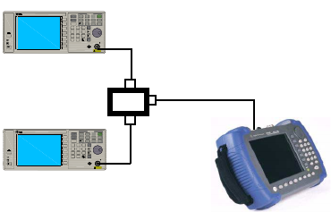
1 Connect two sources to the analyzer input as
shown below.
Figure 3 Setup for obtaining two signals
2 Set one source to 300 MHz. Set the frequency of
the other source to 300.1 MHz. Set both source
amplitudes to
–20 dBm.
3 Set up the analyzer to view the signals:
• Press [PRESET].
• Press [FREQ] > {Center Freq} > 300.05 > {MHz}.
• Press [SPAN] > {Span} > 2 > {MHz}.
• Press [BW/SWP] > {RBW} > 30 > {kHz}.
Frequency
Enter
7
MOD
On/Off
RF
4
1
0
2
9
6
3
On/Off
Amplitude FM
Utility
LF Out
Preset
Local
AM I/Q
File
Trigger
PulseM
·
Sweep
8
5
Remot e
Standby
On
N9310A RF Signal Generator 9 kHz - 3.0 GHz
REVERSE PWR
4W MAX 30 VDC
LF OUT RF OU T 50
FUNCTIONS
Frequency
Enter
7
MOD
On/Off
RF
4
1
0
2
9
6
3
On/Off
Amplitude FM
Utility
LF Out
Preset
Local
AM I/Q
File
TriggerPulseM
·
Sweep
8
5
Remot e
Standby
On
N9310A RF Signal Generator 9 kHz - 3.0 GHz
REVERSE PWR
4W MAX 30VDC
LF OUT RF OU T 50
FUNCTIONS
Directional
coupler
Signal generator
Signal generator