
Option H48 Multiport Test Set User's and Service Guide

5 -20 Agilent Technologies Z5623A Option H48
Performance Verification
Setting Up Limit Testing
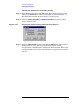
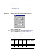
Step 5. The Scale window shown in Figure 5-6 will pop up. When it does, set
the following values:
•Scale Per Division = 5 dB
• Reference Level = 0 dB
• Reference Position = 9 Divisions
When these values have been entered, the Scale window will look like
Figure 5-20. Click the OK button.
Figure 5-20 The Scale Window With Desired Values For Return Loss
Setting Up the Limit Table
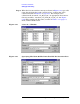
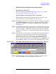
Step 1. Click Trace on the menu bar. When the Trace menu appears, scroll
down to the Limit Test... button and click it. See Figure 5-8.
Step 2. When the Limit Test window pops up as shown in Figure 5-9, click the
Show Table button, then click the OK button.
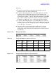
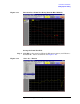
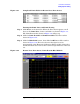
Step 3. When the Limit Table pops up as shown in Figure 5-10, transfer entries
from Table 5-5 to the Limit Table on the network analyzer. (Consult the
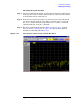
shortcuts listed on page 5-13.) The result is shown in Figure 5-21.
Table 5-5 Limit Table Entries for Return Loss (Port Active)
Segment
Number
Segment
Type
Beginning
Stimulus
Ending
Stimulus
Beginning
Response
Ending
Response
1 Max 300 kHz 1.3 GHz −25.5 dB −25.5 dB
2 Max 1.3 GHz 3 GHz −19 dB −19 dB
3 Max 3 GHz 6 GHz −14.5 dB −14.5 dB
4 Max 6 GHz 9 GHz −9.5 dB −9.5 dB