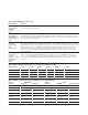
Agilent PN 8510-16 Controlling Test Port Output Power Flatness Product Note UNCORR ECTED P OWER CORREC TED POW ER OUTPUT Agilent 8510C Network Analyzer POWER
Introduction Designers and manufacturers of active devices often need to control the power level at the test port1 of their power-sensitive devices, but find difficulty in overcoming insertion losses. The insertion losses occur as a result of connecting components in the measurement path between the source and the DUT. The Agilent Technologies 8510C is a microwave network analyzer2 capable of setting and controlling the power level at the test port.
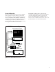
System Configuration The basic 8510C measurement system configuration needed for test port flatness correction is shown in Figure 1. A single channel power meter such as the Agilent 437B, E4418A, or E4418B is required, along with a compatible sensor, for performing the power flatness calibration. Power meters with the 437B command set must be used for the power level flatness correction. The Agilent 8511B frequency converter test set may be used with the test port power flatnesscorrection feature.
Flatness-Correction Operation The basic setup procedure to obtain flat test port output power is illustrated in Table 1. To simplify the execution of the procedure, the front panel hardkeys are enclosed in [brackets]. The softkeys are enclosed in {braces}. Table 2 provides the procedure for setting up the power meter. The network analyzer should be reset before performing any procedures. The flatness-correction calibration can be performed in step, ramp, or frequency list sweep mode.
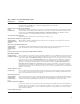
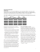
Table 1. Flatness-correction calibration procedure 8510C Keystrokes Description Set up the power meter (see Table 2) For proper operation, the E4418B must be set up before initiating the flatness-correction routine. See Table 2 for specific instructions. Verify the power meter's address on the 8510 system [LOCAL] When shipped from the factory, the address of the power meter is 13. If this conflicts with another instrument on the system bus, {POWERMETER} change the address of the conflicting instrument.
Table 2. Agilent E4418B power meter setup E4418B Keystrokes Description Preset and zero the power meter [PRESET/LOCAL] Return the power meter to a known state. {CONFIRM} [ZERO/CAL] {ZERO} Set up the 437B emulation on the power meter [SYSTEM/INPUTS] The 437B command set must be activated in order to perform the power flatness calibration. Power meters that can be used in {REMOTE INTERFACE} place of the E4418B are the E4418A and 437B.
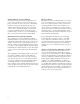
Operational Considerations Calibration time The user may choose to speed up the calibration process by reducing the number of trace points on the analyzer. Table 5 provides some typical calibration times for flatness correction over the full frequency span of the source for different source/test set combinations. Calibration times may be slightly reduced by increasing the stepped measurement speed with the quick step feature on the Agilent 8510C. Table 5.
Verifying a flatness-correction calibration To verify the flatness-correction calibration, the power sensor should be reconnected to the test port to measure the test port power at individual frequencies. Since the measurement system is calibrated in 50W, inaccuracies will occur when a device is not well matched. Since the flatnesscorrection calibration is not a real-time power leveling feature, it cannot correct for mismatches that occur between the test port and the DUT.
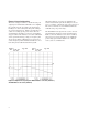
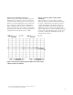
Using test port 1 calibrations on test port 2 In most cases, port 1 will be the input port of the DUT. When port 2 must be used as the input port to the device, the user may choose to use a port 1 flatness-correction calibration on port 2 since the port 1 and port 2 signal paths are symmetrical.1 Figure 3 illustrates the use of port 1 flatness correction on both ports 1 and 2. The port 2 measurement with port 1 flatness-correction calibration is optimized for measurements below 30 GHz.
Practical Application Examples Absolute output power measurements with flatness correction One benefit of the flatness-correction capability is the ability to measure the absolute output power of active devices. Since the input power level to the DUT is kept constant, the magnitude offset feature of the Agilent 8510 can be used to display absolute output power across the entire frequency span of the device.
Amplifier measurement example Step-by-step instructions for setting up and applying flatness corrections for the measurement of an amplifier are shown in Table 7. Gain, absolute output power, and gain compression measurements procedures are covered. For more information on measuring amplifiers, refer to Agilent product note 8510-18, literature number 5963-2352E. Table 7.
Agilent Technologies’ Test and Measurement Support, Services, and Assistance Agilent Technologies aims to maximize the value you receive, while minimizing your risk and problems. We strive to ensure that you get the test and measurement capabilities you paid for and obtain the support you need. Our extensive support resources and services can help you choose the right Agilent products for your applications and apply them successfully. Every instrument and system we sell has a global warranty.