Introduction to New Features Agilent Technologies 8510C Network Analyzer Revision 7.XX (7.
Certification Hewlett-Packard Company certi es that this product met its published speci cations at the time of shipment from the factory. Hewlett-Packard further certi es that its calibration measurements are traceable to the United States National Institute of Standards and Technology (NIST, formerly NBS), to the extent allowed by the Institute's calibration facility, and to the calibration facilities of other International Standards Organization members.
Assistance Product maintenance agreements and other customer assistance agreements are available for Hewlett-Packard products. For any assistance, contact your nearest Hewlett-Packard Sales and Service O ce. Addresses are provided at the back of this manual. General Safety Considerations WARNING Before you turn on this instrument, make sure it has been properly grounded through the protective conductor of the ac power cable to a socket outlet provided with protective earth contact.
1 General Information Introduction to this Document This Introduction to New Features of the HP 8510C is designed to provide you with a quick introduction to the new features and operating details of rmware revision 7.0 or greater of the HP 8510C Network Analyzer. Note A working knowledge of the HP 8510, and basic familiarity with front-panel operation is assumed, and only new features are explained.
Types of Limits There are two limit types: This type of limit consists of two end points with a line drawn between the end points. The end points of the line are de ned by a stimulus value, usually a frequency, and a limit value. The limit line drawn between the two end points may be either at or sloping, depending upon the end point settings. Make certain that you enter an end-point value that is greater than the begin-point value.
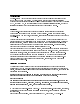
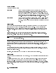
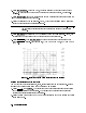
After a limit table has been created for one parameter on one channel, that table may be copied to any other parameter on either of the channels, using the COPY LIMITS function. NNNNNNNNNNNNNNNNNNNNNNNNNNNNNNNNNNN Figure 1-1. Example of a Limit Test using Limit Lines Creating a Limit Test Use the following example to set up an example limit test for an RF lter. Note This procedure assumes a device response is displayed on the network analyzer screen. To Set Up the Measurement 1.
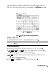
To Set the Limit Test Values Limits create boundaries between which an active trace must remain for the measurement to pass. To develop the limits, you select an appropriate softkey and adjust its position (value) with the RPG, the step keys, or by entering the numeric value via the key pad. 5. Press 4DISPLAY5 then LIMITS . The network analyzer display splits into two sections. One section displays the limit table and the other shows the selected limits on the display. 6.
NNNNNNNNNNNNNNNNNNNNNNNNNNNNNNNNNNN d. Press BEGIN LIMIT and watch the limit segment and measurement trace as you rotate the RPG knob to adjust the beginning of the limit segment. e. Place the beginning of the limit line at 025 dB, which is the device's maximum allowable output power level, for the beginning frequency. Note Notice that the power level and frequency value appear in the limit-test table. You can iterate between setting the beginning and ending of the limit line position.
NNNNNNNNNNNNNNNNNNNNNNNNNNNNNNNNNNNNNN 3. Press END STIMULUS . Enter 150 MHz, the ending frequency of the rst minimum limit line. A limit line is drawn between the two frequency values you entered, at a zero (0.0) unit level. 4. Press BEGIN LIMIT and watch the limit segment and measurement trace as you rotate the RPG knob to adjust the limit segment. 5. Place the beginning of the limit line at 050 dB, which is the device's minimum allowable output power level for the beginning frequency.
3. Press EDIT LIMITS , then press the keys that correspond to the portions of the limit you want to edit (begin frequency, end frequency, begin limit, or end limit, as an example. 4. Enter new limit values. 5. Press 4PRIOR MENU5 to return to the limits menu. 6. Press LIMIT TEST ON to activate the limit test with the new limits. Test results are displayed on the screen as PASS or FAIL.
2 Changing the Calibration Type Introduction You can create new calibration sets from an active two-port calibration set. The two-port set can be a full two-port, a one-path two-port or a TRL two-port calibration set. NNNNNNNNNNNNNNNNNNNNNNNNNNNNNNNNNNNNNNNNNNNNNNNNNNNNNNNNNNNNNNN 2-PORT to: S11 1-PORT creates an S11 1-port calibration from the currently active 2-port calibration set.
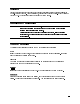
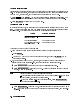
Modifying a Cal Set with Connector Compensation Connector compensation is a feature that provides for compensation of the discontinuity found at the interface between the test port and a connector. The connector here, although mechanically compatible, is not the same as the connector used for the calibration. There are several connector families that have the same characteristic impedance, but use a di erent geometry. Examples of such pairs include: 3.5 mm 3.5 mm SMA 2.4 mm / 2.92 mm / SMA / 2.92 mm / 1.
Figure 2-1.
Using Connector Compensation 1. Press 4CAL5, then press MORE . NNNNNNNNNNNNNN 2. Press MODIFY CAL SET , then press CONNECTOR COMPENSATE . NNNNNNNNNNNNNNNNNNNNNNNNNNNNNNNNNNNNNNNNNNNN Note NNNNNNNNNNNNNNNNNNNNNNNNNNNNNNNNNNNNNNNNNNNNNNNNNNNNNNNNNNNNNN Connector compensation requires that the active Cal Set be a 1-Port or 2-Port calibration. If a Cal Set of any other type is selected, the message ACTIVE CALSET WRONG TYPE appears.
3 Power Domain Measurements Introduction This chapter explains the function and use of power domain in the HP 8510C network analyzer, with rmware revision 7.0, or higher. The following sections explain the concept of power domain, how to set up the HP 8510C to use power domain, the calibration implications, and limitations, as well as detailed measurement examples. This chapter also includes a description of Receiver Cal function, which is required to allow calibrated measurements in power domain mode.
Power Domain Measurements What is Receiver Cal? NNNNNNNNNNNNNNNNNNNNNNNNNNNNNNNNNNNNNN The HP 8510C network analyzer receiver calibration ( RECEIVER CAL ) feature provides a display of unratioed receiver inputs, calibrated in absolute power (usually dBm). The feature is normally used in association with power domain since the power levels displayed are otherwise those determined by the source and do not account for losses in the path between the source and the test ports.
Power Domain Measurements Making a Power Domain Measurement The HP 8510C must already be calibrated in the frequency range of choice, or the user should perform the calibration at the beginning of this power domain procedure. It is recommended that you choose a frequency range that gives frequency steps of a convenient size. Doing so allows the measurement frequencies to be easily recalled later.
Power Domain Measurements Note When in power domain mode, you may use only one Cal Set for 4-parameter display. If power domain is selected with more than one Cal Set applied, then the active parameter calibration is converted to power domain and applied to the measurements. All others are reset. Dual channel display may be used to view power domain data and frequency domain data simultaneously, however, UNCOUPLED CHANNELS must rst be selected.
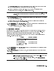
Power Domain Measurements 6. Connect a thru between Port 1 and Port 2 of the HP 8510C. It is not necessary for the thru to be zero length or lossless, but should be appropriately de ned in the selected Cal Kit. 7. In the MENUS block, press 4CAL5, then press RECEIVER CAL . NNNNNNNNNNNNNNNNNNNNNNNNNNNNNNNNNNNNNN a. Press INPUT PWR to measure power at Port 1. The softkey label is underlined after the measurement is completed. b. Press OUTPUT PWR to measure power at Port 2.
Power Domain Measurements Note NNNNNNNNNNNNNN NNNNNNNNNNNNNNNNNNNNNNN Marker search may be used by pressing 4MARKER5, MORE , and MINIMUM . 9. Read the absolute power at the output from the marker readout for Channel 2. Swept-Power Gain Compression Measurement Exercise Making a swept-power gain compression measurement requires using the power domain and receiver calibration features. 1. Set up the HP 8510C for this measurement as for the \Swept-Frequency Gain Compression Measurement Exercise" above.
Power Domain Measurements Note Entering a frequency of measurement not contained in the original frequency domain calibration causes the calibrations to be turned OFF. 11. Repeat steps 8 and 9 above for the new frequency of measurement.