OPERATING MANUAL MULTIPLE OUTPUT LINEAR SYSTEM DC POWER SUPPLY AGILENT MODELS 6625A, 6626A, 6628A, and 6629A Agilent Part No 06626-90001 Microfiche Part No.
CERTIFICATION Agilent Technologies certifies that this product met its published specifications at time of shipment from the factory. Agilent Technologies further certifies that its calibration measurements are traceable to the United States National Bureau of Standards, to the extent allowed by the Bureau's calibration facility, and to the calibration facilities of other International Standards Organization members.
SAFETY SUMMARY The following general safety precautions must be observed during all phases of operation, service, and repair of this instrument. Failure to comply with these precautions or with specific warnings elsewhere in this manual violates safety standards of design, manufacture, and intended use of the instrument. Agilent Technologies assumes no liability for the customer’s failure to comply with these requirements. BEFORE APPLYING POWER.
SAFETY SUMMARY (continued) GENERAL Any LEDs used in this product are Class 1 LEDs as per IEC 825-1. This ISM device complies with Canadian ICES-001. Cet appareil ISM est conforme à la norme NMB-001 du Canada. ENVIRONMENTAL CONDITIONS This instrument is intended for indoor use in an installation category II, pollution degree 2 environment. It is designed to operate at a maximum relative humidity of 95% and at altitudes of up to 2000 meters.
DECLARATION OF CONFORMITY According to ISO/IEC Guide 22 and CEN/CENELEC EN 45014 Manufacturer’s Name and Address Responsible Party Agilent Technologies, Inc. 550 Clark Drive, Suite 101 Budd Lake, New Jersey 07828 USA Alternate Manufacturing Site Agilent Technologies (Malaysia) Sdn.
WHAT THIS MANUAL CONTAINS It contains information relating to the installation, operation, and programming of these supplies as outlined below. Maintenance and troubleshooting instructions are given in a separate Service Manual (Agilent Part No. 06626-90003). Chapter 1.--General Information Chapter 1 contains a general description of the power supplies as well as instrument specifications and information concerning options and accessories. Chapter 2.
Table Of Contents 1 General Information Introduction............................ .......................................................................................................................11 Safety Considerations....................................................................................................................................11 Instrument and Manual Identification.... .......................................................................................................
Table Of Contents (continued) Positive and Negative Voltages.................................................................................................................51 Remote Voltage Sensing..................... ..........................................................................................................51 Remote Sense Connections................... ....................................................................................................52 Output Noise Considerations.........
Table Of Contents (continued) Local Control Of Output Functions...............................................................................................................85 General........................................... ...........................................................................................................85 Setting Voltage and Voltage Range...........................................................................................................
1 General Information Introduction This chapter contains a general description of your power supply as well as its performance specifications. Information about options, accessories, and GP-IB cables is also provided. This manual describes the Agilent 6625A, 6626A, 6628A, and Agilent 6629A power supplies. Unless stated otherwise, the information in this manual applies to all of these models. Information that is specific to one model only is identified as such in this manual.
Accessories 10833A GP-IB cable, 1 m (3.3 ft) 10833B GP-IB cable, 2 m (6.6 ft) 10833C GP-IB cable, 4 m (13.2 ft) 10833D GP-IB cable, 0.5 m (1.6 ft) 10834A GP-IB connector extender Slide mount kit (1494-0059) Description The Agilent power supply features a combination of programming capabilities and linear power supply performance that make them ideal for systems applications. The models in this family offer a total of up to 200 watts of output power, with voltages up to 50 volts and currents up to 2 amps.
The power supplies allow up to a 10 volt sense lead drop. This feature makes them ideal for test system applications where remote sensing is used. The output voltage and current for any output can be monitored with the front panel display. Output specific error messages are also displayed. Front panel annunciators show the operating status of the instrument. The front panel keypad lets you set and readback the voltage limit, current limit, and overvoltage trip level of any output.
Basic Operation Figure 1-2 is a block diagram that illustrates the major assemblies contained within the power supply. As shown in the figure, each supply includes a power transformer, two or more output boards, a GP-IB board, and front panel (display and control keys). Figure 1-2. Block Diagram The appropriate ac input voltage is applied to each output board where it is converted to a raw dc voltage which is subsequently linearly regulated to become the dc output voltage.
Output Boards The output boards are linear dc power supplies. Each isolated output operating boundary curve is shown in Figure 1-1. The ac input to each output board is rectified and applied to a regulator circuit. Each output board employs series regulation techniques. A regulator element is connected in series with the load and operates in the linear region (between saturation and cutoff) of the transistor characteristic curve.
Output response time: Beginning at the time the power supply has finished processing a VSET command (change output voltage), the maximum time for the output voltage to settle to within a settling band about the final value from any specified operating point. This value must be added to the command processing time to obtain total programming time (see Figure 1-3). Time constant is the maximum time required for the voltage to reach 63% of its final value. Figure 1-3.
Table 1-2. Specifications (continued) Source Effect: Voltage + Current 0.5 mV 0.005 mA 0.5 mV 0.005 mA 0.5 mV 0.01 mA 0.5 mV 0.01 mA Programming Accuracy: Note: The programming accuracy specifications may degrade slightly when the unit is subjected to an RF field equal to or greater than 3 volts/meter. Voltage 0.016% + 1.5 mV 0.016% + 10 mV 0.016% + 3 mV 0.016% + 10 mV + Current 0.04% + 15 µA 0.04% + 100 µA 0.04% + 185 µA 0.04% + 500 µA OVP 0.13% + 475 mV 0.13% + 475 mV 0.13% + 475 mV 0.
Table 1-3. Supplemental Characteristics (continued) Output Power Output Range Output Volts Output Amps Lo Range 0-7 V 0-15 mA 25 Watt Output Hi Range 0-50 V 0-500 mA Lo Range 0-16 V 0-200 mA 50 Watt Output Hi Range 0-50 V 0-2 A Temperature Coefficient-Measurement: Voltage ± Current (0.002% + 0.1 mV) per° C +0.5 mV (0.0025% + 1.5 µA) per° C + 1 µA (0.002% + 0.1 mV) per° C +4 mV (0.0025% + 10 µA) per° C + 40 µA (0.002% + 0.1 mV) per° C +1 mV (0.0025% + 20 µA) per° C + 15 µA (0.002% + 0.
Table 1-3. Supplemental Characteristics (continued) High Line Inrush Current: Peak Value rms Value Fuse Rating 100 V Opt 85 A 6.3A 8A 120 V Opt 85 A 5.7 A 8A 220 V Opt 50 A 3.0 A 4A 240 V Opt 50 A 3.0 A 4A GP-IB Interface Capabilities: SH1. AH1, T6, L4, SR1, RL1, PP1, DC1, DT0, C0, E1 Current Sink Capability: 25 Watt output: 0.50 A 50 Watt output: 1.0 A (2.0 A below 16 V) Command Processing Time: (see Figure 1-3) 7 milliseconds typical (with front panel disabled).
Table 1-3. Supplemental Characteristics (continued) Weight: Net Shipping Agilent 6625A, 6628A Agilent 6626A, 6629A 15.5 kg (34 lbs.) 20.8 kg (46 lbs.) 17.7 kg (39 lbs.) 23 kg (51 lbs.) Load Cross Regulation: Voltage 0.25 mV + Current 0.005 mA 20 General Information 0.25 mV 0.005 mA 0.25 mV 0.01 mA 0.25 mV 0.
Figure 1-4.
Figure 1-5. Output Noise (Typical) CC Mode Figure 1-6.
Figure 1-7.
2 Installation Introduction This chapter contains instructions for checking and mounting your power supply, connecting your supply to ac power, converting it from one line voltage to another, and connecting the GP-IB cable. The power supply generates operating magnetic fields which may affect the operation of other instruments. If your instrument is susceptible to magnetic fields, do not locate it in the immediate vicinity of the power supply.
Figure 2-1. Outline Diagram Input Power Requirements You can operate this power supply from a nominal 100 V, 120 V, 220 V or 240 V single phase power source at 47 to 66 Hz. The input voltage range, maximum input current, high line inrush current (PK), and the fuse required for each of the nominal inputs are listed in Table 2-1. You can check the line voltage setting of your supply by examining the door on the line module. This is located on the rear panel of your supply as shown in Figure 2-2.
Figure 2-2. Rear Panel Detail (Agilent 6626A Shown) Table 2-2 Line Fuses Line Fuse Agilent Part Number (for ¼ X 1¼ in. fuses Voltage Needed only) 100/120 V 8AM 2110-0342 220/240 V 4AM 2110-0055 Note: All fuses are rated for 250 V. Figure 2-3.
Power Cord The power supply is shipped from the factory with a power cord that has a plug appropriate for your location. Figure 2-4 shows the standard configuration of plugs used by Agilent Technologies. Below each drawing is the Agilent part number for the replacement power cord equipped with a plug of that configuration. If a different power cord is required, contact the nearest Agilent Technologies Sales and Service office.
FIRE HAZARD. Make sure the replacement fuse is one of the same type (size) and rating (amps) that is consistent with the voltage level you are operating at. Do not use a substitute fuse; use a fuse with the same Agilent Part number listed in Table 2-2. 6. Close the door of the line module and insert the power cord in the ac input socket. Your power supply is now configured to operate at the voltage you selected.
3 Getting Started Introduction This chapter is intended for the first time user of the supply. It provides four main discussions: • • • • Front Panel Controls and Indicators Turning on Your Supply Checking Out Your Supply Using Local Control Introduction to Remote Operation First, the supply’s front panel controls and indicators are briefly described. Some of the controls and indicators will be used in the Turn On And Checkout procedures that follow.
3 5 1 6 7 8 6626A SYSTEM DC POWER SUPPLY SYSTEM VOLTS LCL 45.153 14.235m 1 2 3 4 -- OUTPUT -- CV OUTPUT ENTRY AMPS CC UNR OCP ERR RMT ADDR SRQ ENBLD ADDR RANGE V/I VOLT ERR OVSET VOLT STO OCP RCL RESET CURR CURR OUTPUT SELECT 7 8 9 VSET 4 5 6 ISET 1 2 3 OUTPUT ON/OFF 0 . ENTER LINE ON OFF 9 4 2 Figure 3-1.
Number 4 (cont) Table 3-1. Controls and Indicators (continued) Controls/Indicators Description UNR- Indicates that the selected output channel is unregulated; i.e., it is not regulated by CV or CC control loops. Page 4-4 OCP ENBLD - Indicates that the overcurrent protection function for the selected channel is enabled.
Number 7 Table 3-1. Controls and Indicators (continued) Controls/Indicators Description OUTPUT SELECT - Selects one of the output Output Control Keys channels for local control or display. This key allows the (These twelve keys are channels to be selected in forward (Ð) or reverse (Ï) output dependent). sequence. 34 Getting Started Page 3-7, 3-8, 6-1--6-4 VSET - Displays the selected output’s present voltage setting. The setting can be changed using the numeric entry keys, Ñ VOLT, or Ò VOLT keys..
Number 7 (cont) Table 3-1. Controls and Indicators (continued) Controls/Indicators Description Ñ CURRENT - Increases the selected output current by an LSB and then at a faster rate as the key is kept pressed, or after the RANGE V/I key has been pressed, sets the selected output to the high current range.
Turning On Your Supply The following paragraphs describe the power-on sequence which includes a self test of most of the power supply’s circuits. Before you turn on your supply, make sure that: • • The line module on the rear panel is set to match your input line voltage. The proper fuse is installed and the line cord is plugged in. If you have any questions concerning installation or power requirements, review Chapter 2. To turn on your supply, press the front panel LINE switch.
Figure 3-4. Typical Display at Power-On Self-Test Errors If the supply fails the power-on self-test, all power supply outputs will remain disabled (off) and the display will indicate the type of failure and the output channel on which it occurred. Figure 3-5 shows that self-test detected an error in output channel 3. Error messages that could appear on the display if self-test fails are listed below.
Voltage Test 1. Set the voltage of the selected output to 10 V by pressing: VSET 1 0 ENTER 2. Check that the display reads approximately 10 V and 0 A and the CV annunciator is on indicating that the supply is in the constant voltage mode of operation. Overvoltage Test 1. Program the overvoltage protection (OVP) to 19 V by pressing: OV SET 1 9 ENTER 1 6 ENTER 0 ENTER 2. Set the voltage to 16 V by pressing: VSET 3. Check that the display reads approximately 16 V and 0 A. 4.
6. Check that the display reads approximately 0 volts and the programmable current limit value. Also, check that the front panel CC annunciator is on indicating that the output is in the constant current mode of operation. 7. Set the current to 0.5 A by pressing: ISET . 5 ENTER 8. Check that the display reads approximately 0 V and 0.5 A. 9. Enable the overcurrent protection circuit by pressing: OCP 10.
Enter/Output Statements The programming statements you use to operate your supply from remote depend on your computer and its language. In particular, you need to know the statements your computer uses to output and enter information.
Sending a Remote Command To send the power supply a remote command, combine your computer’s output statement with the GP-IB interface select code, the GP-IB device address, and finally, the power supply command. For example, to set the output voltage of output channel 1 to 2 volts, send: Getting Data From The Supply The supply is capable of measuring the values of its output parameters in response to queries. In this example, the query asks the supply to measure the output voltage at output 1.
Each of these commands is briefly discussed in the following paragraphs to help you get started in programming your supply. To know more about these commands, refer to Chapter 5. The VRSET and IRSET commands select the range the power supply operates in. Two ranges are available for each output - standard resolution, and high resolution (see Table 1-2). If the value for voltage or current entered is not within the present operating range of the supply, the error annunciator will indicate an error.
Output On/Off. You can turn a specified output on or off. Individual outputs can be controlled as shown below. To turn off output 1, send: OUTPUT 705; ’’OUT 1,0" When an output is turned off, it is set to 0 volts and to the minimum current limit value To turn on output 1, send: OUTPUT 705; ’’OUT 1,1" When an output is turned on it will return to the voltage and current settings determined by the present VSET and ISET values. Overvoltage Setting.
4 Output Connections and Operating Information Introduction This chapter explains how to make connections to the output terminals located on the rear of your power supply. Some general operating information is included in this chapter to help you understand how the power supply operates under various load conditions. This information applies whether you are operating the supply via the front panel or the GP-IB.
Operating Quadrants Figures 4-2A and 4-2B show the operating locus of your power supply in three quadrants. The area in quadrant 1 shows the operating locus defined by the voltage and current settings of each output. The area in quadrant 2 indicates the locus where each output can operate as a current sink. You cannot program current limit values in quadrant 2. Figure 4-2.
Figure 4-3 shows the current sink characteristics lower voltages in greater detail. The area in quadrant 4 illustrates the reverse polarity diode characteristics of each output. Do not operate any output with reverse-voltage currents that are greater than the maximum rating of the output. Figure 4-3. Typical Downprogramming Characteristic Below 2.0 V Operating Ranges Notice in Figure 4-2, there are four overlapping areas in quadrant one for both the 25 watt and 50 watt outputs.
The readback resolution of the 25 watt outputs when metering voltages of 7 volts or below, will be 483 µV. For voltages above 7 volts, the readback resolution will be 3.3 mV. The readback resolution of the 25 watt outputs when metering source currents of 15 mA or below, the readback resolution will be 1 µA. When metering source currents above 15 mA, the readback resolution will be 48 µA. When metering sink currents of 15 mA or below, the readback resolution of the 25 watt outputs will be 1 µA.
UNREGULATED OUTPUT -- the supply informs the user when output regulation is not guaranteed. This can occur when attempting to sink excessive currents below 4 volts on 25 W outputs and 2 volts on 50 W outputs or when operating outputs in parallel. The UNR annunciator on the front panel and the UNR bit in the status register indicate that the specified output is unregulated. Line voltage dropout or an incorrectly set ac power module can also cause the output to become unregulated.
Note To prevent tripping of the overvoltage circuit, pick a wire size sufficient to handle the FULL output current of the unit no matter what the intended load current or current limit setting. Table 4-1 lists the resistivity for various wire sizes and the maximum lengths to limit the voltage drop to 1.0 volts for various currents. Table 4-1.
Figure 4-4. Optimum Hookup for Multiple Loads, Local Sensing Note When a load is connected through relay or switch contacts, contact bounce may activate the overvoltage circuit and shut down the supply. Therefore, it is recommended that the output be downprogrammed to 0 or turned-off (disabled) before the relay (or switch) contact is opened or closed.
Figure 4-5. Remote Voltage Sensing The maximum voltage available at the power supply output terminals during remote sensing (see Figure 4-6) is 50.5 volts. This allows the sum of the voltage across both load leads to equal 10 volts maximum. For lower output voltages refer to Figure 4-3. Remote Sense Connections Remember to turn off the power supply before making or changing any connections on the rear panel terminal blocks.
Figure 4-6. Total Allowable Load Lead Voltage Drop (total of both leads) with Remote Sensing Output Noise Considerations Any noise picked up on the sense leads will appear at the supply’s output and may adversely affect CV load regulation. Twist the sense leads or use a ribbon cable to minimize the pickup of external noise. In extremely noisy environments it may be necessary to shield the sense leads. Ground the shield at the power supply end only; do not use the shield as one of the sensing conductors.
Open Sense Leads The sense leads are part of the supply’s feedback path. Connect them in such a way so that they do not inadvertently become open circuited. The power supply includes protection resistors that reduce the effect of open sense leads during remote-sensing operation. If the sense leads open during operation, the supply returns to the local sensing mode, with the voltage at the output terminals approximately equal to the programmed value.
Figure 4-8. External Trigger Circuit Figure 4-9. Equivalent Internal OV Trigger Circuit Power Supply Protection Considerations Battery Charging If you are using your supply in a battery charging application, it is recommended that a series protection diode be added to prevent damage to the supply during an overvoltage shutdown. Remember that each output has an overvoltage protection circuit that fires a crowbar to disable the output for any of the OVERVOLTAGE conditions described on page 48.
Figure 4-10. Recommended Protection Circuit for Battery Charging Capacitive Load Limitation The programmable overvoltage protection circuit can be used to downprogram capacitive loads although it is primarily intended for use as a protection feature as described on page 48. Repetitive (over 100 cycles) tripping of the overvoltage circuit with output capacitors greater than 2000 µF may result in eventual damage to the supply.
Figure 4-11. Parallel Connections with Local Sensing CV Operation For CV operation, one output must operate in CC mode and the other output must operate in CV mode. Although each output operates independently of the other, the output that is operating in CV mode will be ’’controlling" the voltage regulation of both outputs.
CC Operation For CC operation, set the output voltages as outlined in CV operation (page 57), or alternatively, program the voltage settings of both outputs to the same voltage limit point. Then program the current of each output so that the sum of both currents equals the total desired operating current. The simplest way to accomplish this is to program each output to one half of the total desired operating current. Both outputs will operate in the CC mode.
Series Operation SHOCK HAZARD. Floating voltages must not exceed 240 Vdc. No output terminal may be more than 240 Vdc from chassis ground. Connect in series only outputs that have equivalent current ratings. Each output has a reverse voltage protection diode across its output terminals. The current conducted by this diode is not internally limited by the output.
CC Operation For CC operation, the current setting of each output must be programmed to the desired operating current. The sum of the voltage settings determines the voltage limit point. As an example, one way to program the voltage of the output is to set the voltage of each output to one half of the total voltage limit point.
Voltage All series specifications referring to voltage are twice the single output specification except for programming resolution which is the same as for a single output. Current All series specifications referring to current are the same as for a single output except for CC load effect, CC load cross regulation, CC source effect, and CC short term drift which are twice the current programming accuracy (including the percentage portion).
5 Remote Operation Introduction Chapter 3 introduced you to the basics of remote operation and provided a few simple examples using a Series 200/300 computer as the GP-IB controller. This chapter contains all the information required to control your power supply remotely and discusses in greater detail how each of the commands can be implemented. The material covered is intended for any controller capable of using the GP-IB interface functions mentioned in Interface Functions on page 63.
the SRQ annunciator regardless of whether the condition that caused the service request continues to exist. The service request is also removed when you send the "CLR’’ command (see page 76). Remote/Local. The power supply can receive programming information either from the GP-IB (remote) or from the front panel (local). When the power supply is in remote, the state of the supply cannot be changed by using the front panel keys, although the LCL key will remain enabled.
Power-On Service Request (PON) The power supply can request service from the controller when the power is turned on. This request can be enabled or disabled by sending a PON command (see page 80). When the request is enabled, the supply can generate an SRQ at power-on or when there is a momentary loss in power. You can execute a serial poll to clear the service request. Table 5-7 details the conditions under which a PON command will generate an SRQ.
Command Query present hardware error Table 5-1. Power Supply Commands (continued) Header Output Data Range Channel (Fig. 5-2) ERR? --See Table 5-8 Query fault register Syntax Q1 FAULT? 1, 2, 3, 4 --- Q2 ID? --- --- Q1 Program the I DAC in counts IDAC 1, 2, 3, 4 See Service Manual C4 Query setting of I DAC in counts IDAC? 1, 2, 3, 4 --- Q2 Send data to calibrate I circuits IDATA 1, 2, 3, 4 See Table 5-4 C5 Sets output to high I cal.
Command Store present output state Table 5-1. Power Supply Commands (continued) Header Output Data Range Channel (Fig. 5-2) STO 0-10 Query preset status of output Perform self test on GP-IB interface STS? 1, 2, 3, 4 TEST? Syntax C2 Q2 .
Figure 5-2 (Sheet 1 of 2).
Figure 5-2 (Sheet 2 of 2).
Query Header (Note 7) Voltage Setting Current Setting Full Scale Current Range Full Scale Voltage Range Voltage Output Current Output OVP Setting OC Protection On/Off Output On/Off Unmask Setting Delay Setting Status Accumulated Status Fault Error Service Request Setting Power-On SRQ On/Off Display On/Off Model Number Selftest Calibration Mode DC Power On S = Sign Table 5-2.
Initial Conditions Immediately after power on from the factory, the power supply automatically undergoes a self-test and sets all parameters to the values contained in Table 5-3. The values in the first part of the table come from storage register 0 and were stored at the factory. They will remain until STO 0 is used to change settings of the power on state. When the power supply is again turned on, it will initialize its outputs to the values in storage register 0.
VSET 1,.45 If the output channel is operating in constant voltage mode (CV annunciator on) then the actual voltage is the programmed voltage, but in CC mode of operation (CC annunciator on), the programmed voltage is the voltage limit for that output. When programming a value of voltage, the current setpoint will be changed if the total power is greater than the power boundary (see Figure 4-2). Example: ISET 4,1.5 sets current to 1.
Current Programming To program the current, send the output channel and the programmed value in amps. In the example below, output 1 is programmed to 15 mA. ISET 1,0.015 The value you send must always be in amps. For example if you want to program 95 milliamps, convert to amps and then send the command ISET 1,.
Output On/Off The OUT command disables/enables an output channel of the power supply. It will not disturb any other programmed function nor will it reset the protection circuits. You can control individual outputs with the OUT command as shown below. For example, to disable output channel 1 send the following: OUT 1,0 To enable output channel 1 send the following command OUT 1,1 You can find out the present state of output 1 by sending the query: OUT? 1 and addressing the supply to talk.
Overcurrent Protection (OCP) The OCP is a protection feature employed by the power supply to guard against excessive output currents. When the output enters the + CC mode and the OCP is enabled, the OCP circuit down programs the output voltage and disables the output. To enable the OCP, for output channel 1, send the command OCP 1,1 To disable the OCP, send the command OCP 1,0 You can find out the OCP setting by sending the following query and addressing the power supply to talk.
The Clear Command This command will return the power supply to its power-on state and all parameters are returned to their initial power-on values except for the following: 1. The store/recall registers are not cleared. 2. The power supply remains addressed to listen. 3. The PON bit in the serial poll register is cleared To clear the power supply, send the following command: CLR Status Reporting The power supply has the ability to report its internal status to the user whenever it is asked to do so.
Bit Position Bit Weight Meaning Where CV = + CC = - CC = OV = OT = UNR = OC = CP = Table 5-5.
UNMASK 2,XXX where XXX specifies the numeric code (0 to 255) for the unmasked conditions (see Table 5-5). If during operation, the output experiences any of the previously unmasked conditions, it will set the corresponding bit(s) in its fault register. Remember that the bits in the fault register can be set when there is a change in either the status register or the mask register. Each output has its status, mask, and fault registers arranged as shown in Figure 5-3 and Table 5-5.
Service Request Generation When operating your supply, you may want it to request service every time a fault or a programming error condition occurs. To do this you send a service request (SRQ) command. When the condition is true, the power supply responds by setting the RQS bit in the serial poll register, setting the SRQ annunciator on the front panel, and issuing an SRQ over the GP-IB.
The ability to generate service requests can be enabled or disabled using the SRQ command as described below. To disable the service request capability, except for power-on, send: SRQ 0 To enable the service request capability for all output faults, send: SRQ 1 To enable the service request capability for errors, send: SRQ 2 To enable the service request capability for both faults and errors, send: SRQ 3 The Power-On Service Request.
Reprogramming delay will delay the onset of certain fault conditions and prevent the power supply from registering a fault when these conditions are true. When the delay is in effect, the CV, + CC, - CC and UNR bits of the status register are masked and cannot communicate with the mask and fault registers and the OCP function. This will prevent the supply from registering a fault should any of these bits become set during the delay period.
Other Queries In the examples discussed above, you saw how to use queries for each function discussed. The following paragraphs describe other queries which were not previously covered. ERROR Query. The power supply can detect both programming and hardware errors. You can use either the front panel (see page 89) or the GP-IB to find out the type of error. Upon detecting an error, the error annunciator on the front panel and the ERR bit in the serial poll register will be set.
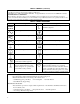
To enable all outputs in constant current mode at turn on send: DCPON 2 To disable all outputs in constant current mode at turn-on send: DCPON 3 Front Panel Response NO ERROR GP-IB Code 0 Table 5-8. Error Messages Explanation This is the response to the ERR? query when there are no errors. INVALID CHAR 1 You sent the supply a character it did not recognize. INVALID NUM 2 Format of your number is incorrect. Check number syntax.
Table 5-8. Error Messages (continued) Explanation Front Panel Response HDW ERR CH 1 GP-IB Code 11 HDW ERR CH 2 12 Same as in Error #11. HDW ERR CH 3 13 Same as in Error #11. HDW ERR CH 4 14 Same as in Error #11. NO MODEL NUM 15 The interface cannot find its model number. There may be a hardware failure or the instrument may require reprogramming. Service is required. CAL ERROR 16 You tried to use either a calibration command with CMODE off or the calibration failed while in CMODE.
6 Local Operation Introduction Chapter 3 introduced you to the supply’s front panel controls and indicators to help you turn on the supply and perform the checkout procedures that were given in that chapter. The following paragraphs describe how to use all of the front panel controls and indicators. Most of the remote operations described in Chapter 5 can also be performed locally from the supply’s front panel.
OUTPUT ANNUNCIATOR CHANNEL 1 LOCAL MODE KEY DISPLAY OUTPUT FUNCTION KEYS 6626A SYSTEM DC POWER SUPPLY SYSTEM VOLTS LCL 45.153 14.235m 1 2 3 4 -- OUTPUT -- CV OUTPUT ENTRY AMPS CC UNR OCP ERR RMT ADDR SRQ ENBLD ADDR RANGE V/I VOLT ERR OVSET VOLT STO OCP RCL RESET OUTPUT SELECT CURR CURR 7 8 9 VSET 4 5 6 ISET 1 2 3 OUTPUT ON/OFF 0 . ENTER LINE ON OFF SYSTEM FUNCTION KEYS NUMERIC ENTRY KEYS Figure 6-1.
The voltage step keys can also be used to change the voltage setting. VSET ÑVOLT ÒVOLT or then ENTER The voltage can be set in the immediate execute mode. This mode is in effect when background metering is in effect. Pressing ÑVOLT or ÒVOLT will change the setting and the effect on the voltage and current can be observed on the display. The voltage range can be changed by using the RANGE V/I key and the voltage step keys.
Setting Overvoltage Protection Programmable overvoltage protection (OVP) guards your load against overvoltage by crowbarring and downprogramming the power supply output if the programmed overvoltage setting is exceeded. A fixed OV circuit with a trip level about 20 percent above the maximum programmable voltage acts as a backup to the programmable OVP. When overvoltage protection is activated, the output is shorted and the message ’’OVERVOLTAGE’’ will appear on the front panel display.
For example, you can change the address of your supply to 10 by pressing: ADDR 1 0 ENTER Displaying Error Messages The power supply can detect both programming and hardware errors. Upon detecting an error, the ERR annunciator on the front panel comes on and the ERR bit in the serial poll register will be set (see page 78). When an error is detected, you can display the error message by pressing the ERR key. The power supply will return the error message to the display and clear the error bit.
A Alignment Procedures Introduction This appendix contains the software alignment procedures for the power supply. These supplies should be aligned twice a year, or whenever certain repairs are made (see Service Manual). The equipment that you need and the test setups to perform the alignment are also shown. A listing of the alignment procedure appears at the end of Appendix A. Refer to Appendix C (Command Summary) for detailed explanations of the commands used within the alignment program.
The program contains embedded comments (identified by a leading asterisk {! } ) which explain various sections and procedures. To reduce keystroking, the program may be shortened to a minimum number of lines by eliminating these comments. The alignment program is available on a 5¼ floppy (Agilent P/N 06626-10001) or 3½ inch microfloppy (Agilent P/N 06626-10002).
After testing of a channel is completed, the program will check if any errors have occurred (the subprogram is called in line 850 and performed in lines 3670 - 3780). If an error has occurred, a message will be sent to the output device (CRT). After all outputs are tested without errors, the CAL MODE will be turned off, and the calibration constants stored.
Figure A-3 Figure A-4 Figure A-5 94 Alignment Procedures
Alignment Program 10 ! This program called "ALIGN_6626" will align 20 ! the Agilent6625A, 26, 28 and 29A Power Supplies It 30 ! requires an Agilent3458A DMM and a four terminal 40 ! 0.1 ohm current shunt accurate to +/-50 ppm 50 ! 60 ! May 06,l989 Rev A.03.
Alignment Program (continued) 530 540 550 560 Chan=1 570 Other_chan=2 580 Get_data 590 Cal_sink(Irng_hi,1) 600 ! 610 Chan=2 620 Other_chan=1 630 Get_data 640 Cal_sink(Irng_hi,-1) 650 ! 660 IF No_of_outputs=4 THEN 670 Chan=3 680 Other_chan=4 690 Get_data 700 Cal_sink(Irng_lo,1) 710 ! 720 Chan=4 730 Other_chan=3 740 Cal_sink(Irng_lo,-1) 750 ! 760 Chan=3 770 Other_chan=4 780 Cal_sink(Irng_hi,1) 790 ! 800 Chan=4 810 Other_chan=3 820 Cal_sink(Irng_hi,-1) 830 END IF 840 : 850 Check_error 860 Cal_mode_off 870 ! 88
Alignment Program (continued) 1050 ! 1060 ! 1070 ! 1080 DEF FNDci(I_range) ! Function to read current 1090 COM /Vm/ @Vm 1100 COM /Shunt/ Shunt_r 1110 IF I_range=2 THEN ! 2A must read across shunt 1120 Amps=FNDcv/Shunt_r ! Convert shunt voltage to Amps 1130 ELSE! ! <2A read direct from DMM 1140 OUTPUT @Vm;"DCI" ! Set DMM to read DC current 1150 TRIGGER @Vm ! Take a current reading 1160 ENTER @Vm;Amps ! Enter the current 1170 END IF 1180 RETURN Amps ! Return the current reading 1190 FNEND 1200 ! 1210 ! 1220 !
Alignment Program (continued) 1570 PRINT "Press CONTINUE when ready 1580 PAUSE 1590 Output_on 1600 ! 1610 Cal_v: ! 1620 Clear_screen 1630 PRINT "Calibrating the";V_range;"volt range programming” 1640 ! 1650 OUTPUT @Ps;"VRSET" ;Chan,V_range ! Set voltage range 1660 ! 1670 OUTPUT @Ps; VLO";Chan ! Set to low output voltage 1680 WAIT 1 ! Wait for supply to stabilize 1690 Vlo=FNDcv ! Read low voltage 1700 ! 1710 OUTPUT @Ps; “VHI” ;Chan ! Set to high output voltage 1720 WAIT 1 ! Wait for supply to stabilize 1730
Alignment Program (continued) 2090 ! 2100 ! 2110 Cal_current: SUB Cal_current(I_range) ! Subprogram to cal current 2120 COM /Ps/ Chan,Other_chan,@Ps,Model$[7] 2130 ! 2140 IF I_range= .
Alignment Program (continued) 2610 Irlo=FNDci(I_range) ! Read low output current 2620 ! 2630 OUTPUT @Ps;"IRHI";Chan ! Set high readback current 2640 REPEAT ! Wait for supply to finish 2650 UNTIL BIT(SPOLL(@Ps),4) ! Finished when Bit 4 goes true 2660 Irhi=FNDci(I_range) ! Read high output current 2670 ! 2680 OUTPUT @Ps;"IRDAT";Chan,Irlo,Irhi ! Send current readback data 2690 ! 2700 SUBEND 2710 ! 2720 ! 2730 ! 2740 Cal_sink SUB Cal_sink(I_range,Polarity) ! Subprogram to cal -CC 2750 COM /Ps/ Chan,Other_chan,@
Alignment Program (continued) 3130 PRINT "Calibrating output";Chan;"";I_range;"A current sink readback" 3140 ! 3150 OUTPUT @Ps;"IRSET";Chan,I_range;";IRSET";Other chan,I_range 3160 ! Set I range for source and 3170 ! sink range 3180 OUTPUT @Ps; “ISET”;Other_chan,0;”;VSET”;Other_chan,7 3190 ! Set source V & I output 3200 Output_on 3210 WAIT 1 ! Wait for source to stabilize 3220 ! 3230 OUTPUT @Ps;"IRLN";Chan ! Set sink readback low 3240 REPEAT ! Wait for supply to finish 3250 UNTIL BIT(SPOLL(@Ps),4) ! Finishe
Alignment Program (continued) 3650 ! 3660 ! 3670 Check_error:SUB Check_error ! Subprogram to check for errors 3680 COM /Ps/ Chan,Other_chan,@Ps,Model$[7] 3690 Clear_screen 3700 PRINT “Checking for errors” 3710 OUTPUT @Ps;”ERR?” ! Query supply for errors 3720 ENTER @Ps;Err ! Enter the error number 3730 IF Err>0 THEN ! If an error then print msg 3740 PRINT “Error”;Err;”occurred.
B Programming With a Series 200/300 Computer Introduction The purpose of this appendix is to serve as an introduction to programming your power supply with an HP Series 200/300 computer using the BASIC language. Examples are included that employ some of the most frequently used functions. These examples have been written so that they will run on all power supplies. The values used in the examples (5 V and 0.5 A for instance), are within the operating locus of all outputs on all models.
VOLTAGE AND CURRENT PROGRAMMING WITH VARIABLES You can use variables in a program to represent data values in the device commands. This is useful in applications that require changing the voltage and current values to different predetermined settings. The following program uses a variable in a FOR NEXT loop to ramp up output voltage in 0.1 volt steps from 0 to 5 volts. 10 ASSIGN @Ps TO 705 20 OUTPUT @Ps;"CLR;ISET1,0.5" 30 FOR Voltage=0 TO 5 STEP 0.1 40 OUTPUT @Ps;’’VSET1,";Voltage 50 WAIT 0.
10 ASSIGN @Ps TO 705 20 OUTPUT @Ps;’’VSET?1’’ 30 ENTER @Ps;Vsl 40 OUTPUT @Ps;"ISET?1" 50 ENTER @Ps;Isl 60 PRINT ’’VOLTAGE SETTING OF OUTPUT #1 = ";Vsl 70 PRINT "CURRENT LIMIT SETTING OF OUTPUT #1 = ";Isl 80 END Line 10: Line 20,30: Line 40,50: Line 60,70: Assigns the I/O pathname to the power supply. Queries the supply for output 1’s voltage setting. You cannot string multiple queries together in a single device command because the power supply can only return the most recently queried data.
Service Request and Serial Poll The fault and mask registers, when used in conjunction with the service request and serial poll functions, allow you to select which conditions can cause computer interrupts. The fault and mask registers can also be used independently of the serial poll or service request if so desired. The following example shows how to enable an interrupt to the computer in the case of an overvoltage condition.
Error Detection The power supply can recognize programming errors and can inform you when a programming error occurs. When an error is detected, no attempt is made to execute the command. Instead, a bit in the serial poll register is set. If SRQ2 or SRQ3 is set, an interrupt will be generated. The following program checks for programming errors and can be entered and run as is. While it is running, commands can be sent to the power supply from the keyboard.
LINE 10: LINE 20: LINE 30: LINE 40: LINE 80: LINE 90: LINE 100: LINE 110,120: LINE 130: LINE 140,150: LINE 170-420: Assigns the I/O path name to the power supply. Declares a common block for the I/O path name. Defines interrupt on softkey depression and branch to error routine. Idles on softkey definition. Defines subprogram Err _ trap Disables interrupt capability while processing. Brings in the common block for the I/O pathname. Enters error code from power supply. Clears computer screen.
C Command Summary Introduction For convenience, a “quick reference” listing tabulating general command headers, and calibration command headers is shown at the beginning of Table C-1 (page 110). (Note that calibration commands are described in detail in Appendix A.) Table C-2 (pages 111-115) provides an alphabetical listing and a brief description of each command that may be sent to the power supplies. Chapter 5 gives a complete description (including syntax) of most of the commands listed.
Table C-1 Quick Reference Listing of Commands General Commands * * ** * ** ** ** * ASTS? < ch > CLR CMODE < 1 (on) or 0 (off) > CMODE? DCPON < 1 (on) or 0 (off) > DLY < ch >, < delay time > DLY? < ch > DSP < 1 (on) or 0 (off)> DSP <"string"> DSP? ERR? FAULT? < ch > ID? IOUT? IRSET , IRSET? < ch > ISET < ch >, < current setting > ISET? ISTEP < ch >, < step value > METER < ch > METER? OCP < ch >, < 1, (on) or 0 (off) > OCP? < ch > OCRST * ** * ** * ** ** ** ** ** OUT < ch >, <
ASTS? < ch > Table C-2 Command Summary Queries the accumulated status (ASTS) of the specified output < ch > . The response (integer 0-255) represents the sum of the binary weights of the ASTS register bits (see page 77). The ASTS register is automatically set to the present status after being queried. CLR Returns the entire power supply (all outputs) to the power on state, except that the supply is not unaddressed and its store/recall registers are not changed (see page 76).
ID? Table C-2 Command Summary (continued) Queries the identification (model number) of the supply. (see page 82). IDATA < ch >, < Ilo > , < Ihi > Sends data to calibrate the current setting circuits of the specified output < ch >. Ilo and Ihi are measured values which the supply uses to calculate correction constants (see Appendix A). IHI < ch > Causes the current of the specified output < ch > to go to the high calibration point (see Appendix A).
NIDAT < ch > . < Ilo > . < Ihi > Table C-2 Command Summary (continued) Sends data to calibrate - current readback for the selected output < ch > . This command must be sent after IRLN and IRHN commands. OCP < ch >, < x > Enables the over current protection circuit protection circuit for the specified output < ch >. This circuit, when enabled, causes the output to go to the off state when the output is on the + CC mode. On/off is a 1 to turn on (enable) or a 0 to turn off (disable) the circuit.
ROM? Table C-2 Command Summary (continued) Queries the revision date of the power supply’s firmware. See service manual. SROM? Queries the revision date of the secondary ROM. See service manual. SRQ Sets the causes for generating SRQ. Setting < x > can be a 0, 1, 2, or 3 as described on page 79. SRQ? Queries the present setting of the reasons for issuing an SRQ (see page 79). Response is 0, 1, 2, or that corresponds with the settings for SRQ.
VMUX? < ch > , < x > Table C-2 Command Summary (continued) Queries the measurement of the input < x > to the analog multiplexer on the specified output < ch > (see Appendix A). VOUT? < ch > Queries the measured output voltage of the specified output < ch > (see page 70). The response is a real number. The front panel display can be used to monitor the measured output voltage (and current) of the selected output channel.
D Error Codes and Messages Introduction This appendix describes the GP-IB error codes that can be readback to the controller and the error messages that can be displayed on the power supply’s front panel. A brief explanation of each code and message is also given. The error codes and/or messages fall into three categories: Power-on Self Test Messages, responses to the ERR? query, and responses to the TEST? query.
Table D-2. ERROR Responses (continued) Explanation Error Code (ERR? query) Message (ERR key) 3 INVALID STR 4 SYNTAX ERROR You sent a command with improper syntax. Check syntax of your command (see Chapter 5). 5 NUMBER RANGE An out of range number was sent. Send a new number within the legal range. 6 NO QUERY The computer addressed the supply to talk, but it did not first request data. Send query first and then address the supply to talk.
Error Code (ERR? query) Message (ERR key) Table D-2. ERROR Responses (continued) Explanation 18 CAL LOCKED Calibration was attempted with the calibration jumper on the GP-IB board in the lockout position (See Section IV in the Service Manual). Reposition the jumper and re-calibrate if this is desired. 22 SKIP SLF TST The self test jumper on the GP-IB board is in the Skip Self Test Position (See Section IV in the Service Manual). Reposition the jumper and carry out self-test if this is desired.
E Manual Backdating Introduction The backdating information in this chapter applies to units that have the following serial numbers: Agilent Model 6625A. serials 2831A-00101 to 00663 Agilent Model 6626A, serials 2831A-00101 to 00823 Agilent Model 6628A, serials 2922A-00101 to 00232 Agilent Model 6629A, serials 2920A-00101 to 00292 Make Changes On page 29, replace the information in Line Voltage Conversion paragraph under steps number 2, 3, and 4 as follows: 2.
Agilent Sales and Support Office For more information about Agilent Technologies test and measurement products, applications, services, and for a current sales office listing, visit our web site: http://www.agilent.com/find/tmdir You can also contact one of the following centers and ask for a test and measurement sales representative. United States: Agilent Technologies Test and Measurement Call Center P.O.
Manual Updates The following updates have been made to this manual since the print revision indicated on the title page. 2/01/00 All references to HP have been changed to Agilent. All references to HP-IB have been changed to GPIB. 9/20/04 The Declaration of Conformity has been updated.