
User's Manual

Using the Matrix Modules 39Chapter 3
Scanning Channels
Scanning matrix module channels consists of closing a sequence of
channels one channel at a time. Single scan, multiple scans, or continuous
scanning modes are available. TRIGger:SOURce specifies the source to
advance the scan. OUTPut can be used to enable the E1406A Command
Module Trig Out port or TTL Trigger bus lines (0-7).
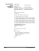
Example: Scanning
Channels Using
TTL Triggers
(BASIC)
This example uses the E1406A Command Module TTL Trigger Bus Lines
to synchronize matrix module channel closures to an E1412A system
multimeter. For measurement synchronization, the E1406A TTL Trigger
Bus Line 0 is used by the matrix module to trigger the multimeter to perform
a measurement. The E1406A TTL Trigger Bus Line 1 is used by the
multimeter to advance the matrix module channel scan.
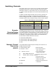
Note that these trigger bus lines are not actual hardware connections.
Triggering is accomplished by the E1406A firmware. Row 00 (High and Low)
of an E1465A 16x 6 matrix module is connected to the voltmeter's High and
Low. The columns are then scanned, switching in different DUTs (devices
under test).
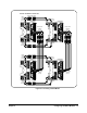
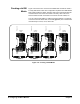
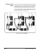
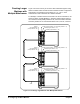
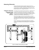
Figure 3-1 shows how to connect the matrix module to the multimeter
module. The connections shown with dotted lines are not actual hardware
connections, but indicate how the firmware operates to accomplish the
triggering.
Figure 3-1. Example: Scanning Using TTL Triggers
E1406A
Command Module
Multimeter Module
E1412A
E1466A
Terminal Module
HI
LO
Matrix Module
E1466A
Row 00H
Row 00L
Complete
Trigger
TTLTrg1
TTLTrg0
VM
TTLTrg1
TTLTrg0