Agilent 6000 Series Oscilloscopes Programmer’s Quick Start Guide Agilent Technologies
Notices © Agilent Technologies, Inc. 2005-2007 Warranty No part of this manual may be reproduced in any form or by any means (including electronic storage and retrieval or translation into a foreign language) without prior agreement and written consent from Agilent Technologies, Inc. as governed by United States and international copyright laws. The material contained in this document is provided “as is,” and is subject to being changed, without notice, in future editions.
Programming the Oscilloscope—At a Glance You can automate 6000 Series oscilloscope setup and data capture by running programs on a controller PC. Just install the Agilent IO Libraries Suite software, connect the oscilloscope (using USB, LAN, or GPIB interfaces), and begin writing programs. The Agilent IO Libraries Suite provides SICL, VISA, and VISA COM libraries for programming instruments. You can use these libraries from C/C++ or Visual Basic programs.
In This Book This Programmer’s Quick Start Guide is your introduction to programming the oscilloscope using an instrument controller PC. This book and the Programmer’s Reference, which is supplied as a Microsoft Windows help file on CD, describes the 6000 Series oscilloscope’s programming interface. This book contains the following information: • Chapter 1, “Setting Up”, describes the steps you must take before you can program the oscilloscope.
Contents 1 Setting Up Step 1. Install Agilent IO Libraries Suite software Step 2. Connect and set up the oscilloscope Using the USB (Device) Interface 9 Using the LAN Interface 9 Using the GPIB Interface 10 Step 3. Verify the oscilloscope connection 8 11 Step 4.
Reading Definite-Length Block Query Response Data Sending Multiple Queries and Reading Results 27 Checking Instrument Status 27 Other Ways of Sending Commands 28 Telnet Sockets 28 Sending SCPI Commands using Browser Web Control 26 28 Index 6 Agilent 6000 Series Oscilloscopes Programmer’s Quick Start Guide
Agilent 6000 Series Oscilloscopes Programmer’s Quick Start Guide 1 Setting Up Step 1. Install Agilent IO Libraries Suite software 8 Step 2. Connect and set up the oscilloscope 8 Step 3. Verify the oscilloscope connection 11 Step 4. Access the Programmer’s Reference 14 This chapter explains how to install the Agilent IO Libraries Suite software, connect the oscilloscope to the controller PC, set up the oscilloscope, verify the oscilloscope connection, and access the online Programmer’s Reference.
1 Setting Up Step 1. Install Agilent IO Libraries Suite software Insert the Automation-Ready CD that was shipped with your oscilloscope into the controller PC’s CD-ROM drive, and follow its installation instructions. You can also download the Agilent IO Libraries Suite software from the web at: http://www.agilent.com/find/iolib Step 2. Connect and set up the oscilloscope The 6000 Series oscilloscope has three different interfaces you can use for programming: USB (device), LAN, or GPIB.
Setting Up 1 Using the USB (Device) Interface 1 Connect a USB cable from the controller PC’s USB port to the “USB DEVICE” port on the back of the oscilloscope. This is a USB 2.0 high speed port. 2 On the oscilloscope, verify that the controller interface is enabled: a Press the Utility button. b Using the softkeys, press I/O and Controller. c Ensure the box next to USB is selected( ). If not( ), use the Entry knob to select USB; then, press the Control softkey again.
1 Setting Up Using the GPIB Interface 1 Connect a GPIB cable from the controller PC’s GPIB interface to the “GPIB” port on the back of the oscilloscope. 2 On the oscilloscope, verify that the controller interface is enabled: a Press the Utility button. b Using the softkeys, press I/O and Controller. c Ensure the box next to GPIB is selected( ). If not( ), use the Entry knob to select GPIB; then, press the Control softkey again.
Setting Up 1 Step 3. Verify the oscilloscope connection 1 On the controller PC, click on the Agilent IO Control icon in the taskbar and choose Agilent Connection Expert from the popup menu. 2 In the Agilent Connection Expert application, instruments connected to the controller’s USB and GPIB interfaces should automatically appear. (You can click Refresh All to update the list of instruments on these interfaces.
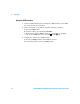
1 Setting Up You must manually add instruments on LAN interfaces: a Right-click on the LAN interface, choose Add Instrument from the popup menu, and click OK in the resulting dialog (because the desired interface is already selected). b In the next LAN Instrument dialog, select either Hostname or IP address, and enter the oscilloscope’s hostname or IP address. c Click Test Connection. d If the instrument is successfully opened, click OK to close the dialog.
Setting Up 1 b In the Agilent Interactive IO application, enter commands in the Command field and press Send Command, Read Response, or Send & Read. c Choose Connect>Exit from the menu to exit the Agilent Interactive IO application. 4 In the Agilent Connection Expert application, choose File>Exit from the menu to exit the application.
1 Setting Up Step 4. Access the Programmer’s Reference The Programmer’s Reference is supplied on CD as a help file readable with the Microsoft Windows help viewer. The Programmer’s Reference help file describes oscilloscope command syntax and status reporting data structures. It also contains sample programs that you can cut-and-paste from. To access the Programmer’s Reference help file The Programmer’s Reference help file requires Microsoft Windows 95/98/NT/2000/XP.
Agilent 6000 Series Oscilloscopes Programmer’s Quick Start Guide 2 Getting Started Basic Oscilloscope Program Structure 16 Programming the Oscilloscope 18 This chapter gives you an overview of programming the 6000 Series oscilloscopes. It describes basic oscilloscope program structure and shows how to program the oscilloscope using a few simple examples. The getting started examples show how to send oscilloscope setup, data capture, and query commands, and they show how to read query results.
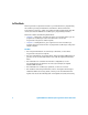
2 Getting Started Basic Oscilloscope Program Structure The following figure shows the basic structure of every program you will write for the oscilloscope. Initializing To ensure consistent, repeatable performance, you need to start the program, controller, and oscilloscope in a known state. Without correct initialization, your program may run correctly in one instance and not in another.
Getting Started 2 Capturing Data Once you initialize the oscilloscope, you can begin capturing data for analysis. Remember that while the oscilloscope is responding to commands from the controller, it is not performing acquisitions. Also, when you change the oscilloscope configuration, any data already captured will most likely be rendered. To collect data, you use the :DIGitize command. This command clears the waveform buffers and starts the acquisition process.
2 Getting Started Programming the Oscilloscope Referencing the IO Library No matter which instrument programming library you use (SICL, VISA, or VISA COM), you must reference the library from your program. In C/C++, you must tell the compiler where to find the include and library files (see the Agilent IO Libraries Suite documentation for more information).
2 Getting Started Opening the Oscilloscope Connection via the IO Library PC controllers communicate with the oscilloscope by sending and receiving messages over a remote interface. Once you have opened a connection to the oscilloscope over the remote interface, programming instructions normally appear as ASCII character strings embedded inside write statements of the programing language. Read statements are used to read query responses from the oscilloscope.
2 Getting Started Initializing the Interface and the Oscilloscope To make sure the bus and all appropriate interfaces are in a known state, begin every program with an initialization statement. When using the Agilent VISA COM library, you can use the resource session object’s Clear method to clears the interface buffer: Dim myMgr As VisaComLib.ResourceManager Dim myScope As VisaComLib.FormattedIO488 Set myMgr = New VisaComLib.ResourceManager Set myScope = New VisaComLib.
2 Getting Started Using Other Oscilloscope Setup Commands A typical oscilloscope setup would set the vertical range and offset voltage, the horizontal range, delay time, delay reference, trigger mode, trigger level, and slope. An example of the commands that might be sent to the oscilloscope are: myScope.WriteString myScope.WriteString myScope.WriteString myScope.WriteString myScope.WriteString myScope.WriteString “:CHANNEL1:PROBE 10" “:CHANNEL1:RANGE 16" “:CHANNEL1:OFFSET 1.
2 Getting Started Capturing Data with the :DIGitize Command The :DIGitize command captures data that meets the specifications set up by the :ACQuire subsystem. When the digitize process is complete, the acquisition is stopped. The captured data can then be measured by the instrument or transferred to the controller for further analysis. The captured data consists of two parts: the waveform data record, and the preamble.
Getting Started 2 The following program example shows a typical setup: myScope.WriteString myScope.WriteString myScope.WriteString myScope.WriteString myScope.WriteString myScope.WriteString myScope.WriteString myScope.WriteString ":ACQUIRE:TYPE AVERAGE" ":ACQUIRE:COMPLETE 100" ":ACQUIRE:COUNT 8" ":DIGITIZE CHANNEL1" ":WAVEFORM:SOURCE CHANNEL1" ":WAVEFORM:FORMAT BYTE" ":WAVEFORM:POINTS 500" ":WAVEFORM:DATA?" This setup places the instrument into the averaged mode with eight averages.
2 Getting Started Reading Query Responses from the Oscilloscope After receiving a query (command header followed by a question mark), the instrument interrogates the requested function and places the answer in its output queue. The answer remains in the output queue until it is read or another command is issued. When read, the answer is transmitted across the interface to the designated listener (typically a controller).
Getting Started 2 Reading Query Results into String Variables The output of the instrument may be numeric or character data depending on what is queried. Refer to the specific command descriptions in the online Programmer’s Reference for the formats and types of data returned from queries. NOTE Express String Variables Using Exact Syntax In Visual Basic, string variables are case sensitive and must be expressed exactly the same each time they are used.
2 Getting Started Reading Definite-Length Block Query Response Data Definite-length block query response data allows any type of device-dependent data to be transmitted over the system interface as a series of 8-bit binary data bytes. This is particularly useful for sending large quantities of data or 8-bit extended ASCII codes. The syntax is a pound sign (#) followed by a non-zero digit representing the number of digits in the decimal integer.
2 Getting Started Sending Multiple Queries and Reading Results You can send multiple queries to the instrument within a single command string, but you must also read them back as a single query result. This can be accomplished by reading them back into a single string variable, multiple string variables, or multiple numeric variables. For example, to read the :TIMebase:RANGe?;DELay? query result into a single string variable, you could use the commands: myScope.
2 Getting Started Other Ways of Sending Commands Standard Commands for Programmable Instrumentation (SCPI) can be sent via a Telnet socket or through the Browser Web Control. Telnet Sockets The following information is provided for those programmers who wish to control the oscilloscope with SCPI commands in a Telnet session. To connect to the oscilloscope via a telnet socket, issue the following command: telnet 5024 where is the hostname of the oscilloscope.
Index Numerics F O 82350A GPIB interface, 4 FormattedIO488 object, 19 frequency measurement, 17 on the web, 14 Open method, 19 oscilloscope command syntax, 14 connecting, 8 connection, opening, 19 initialization, 16 operation, 4 program structure, 16 setting up, 8 setup, 21 verifying connection, 11 A ACQuire subsystem, 22 Addresses softkey, 9 Agilent Connection Expert, 11 Agilent Interactive IO application, 13 Agilent IO Control icon, 11 Agilent IO Libraries Suite, 3, 4, 7, 18, 20 installing, 8 analyz
Index ReadString method, 19, 24 resource session object, 20 ResourceManager object, 19 S sample programs, 14 SCPI commands, 28 set up oscilloscope, 8 SICL library, 3 status registers, 27 status reporting data structures, 14 string variables, 25 reading multiple query results into, 27 reading query results into multiple, 27 subnet mask, 9 syntax, command, 14 T Telnet sockets, 28 TIMebase:MODE, 22 U USB (Device) interface, 8, 9 User’s Guide, 4 Utility button, 9, 10 V VBA, 18 VISA COM library, 3 VISA libr
Index Agilent 6000 Series Oscilloscopes Programmer’s Quick Start Guide 31
Index .