Agilent 75000 SERIES B Agilent E1364A 16-Channel Form C Switch Module User’s Manual Copyright© Agilent Technologies, Inc.
Contents Agilent E1364A Switch Module Table of Contents Warranty . . . . . . . . . . WARNINGS . . . . . . . . Safety Symbols . . . . . . Declaration of Conformity . . . . . . . . . . . . . . . . . . . . . . . . . . . . . . . . . . . . . . . . . . . . . . . . . . . . . . . . . . . . . . . . . . . . . . . . . . . . . . . . . . . . . . . . . . . . . . . . . . . . . . . . . . . . . . . . . . . . . . . . . . . . . . . . . 5 6 6 7 1. Agilent E1364A Getting Started . . . . . . . .
Storing States . . . . . . . . . . . . . . . . . . . . . . . . . . . . . . . . . . . . . 39 Recalling States . . . . . . . . . . . . . . . . . . . . . . . . . . . . . . . . . . . . 39 SCPI Error Responses . . . . . . . . . . . . . . . . . . . . . . . . . . . . . . . . . . . 40 5. Agilent E1364A Form C Switch Command Reference . . . . . . . . . . . . . . . . . . . . . 41 Using This Chapter . . . . . . . Command Types . . . . . . . . . Common Command Format SCPI Command Format . . Command Separator . . . .
IEEE 488.2 Common Commands . . . . . . . . . . . . . . . . . . . . . . . . . . . . . 61 Command Quick Reference . . . . . . . . . . . . . . . . . . . . . . . . . . . . . . . . 62 A. Agilent E1364A Specifications . . . . . . . . . . . . . . . . . . . . . . . . . . . . . . . . . 63 Relay Life . . . . . . . . . . . . . . . . . . . . . . . . . . . . . . . . . . . . . . . . . 64 End of Life Detection . . . . . . . . . . . . . . . . . . . . . . . . . . . . . . . . . 64 Replacement Strategy . . . . . . . . . . . .
Notes 4 Agilent E1364A Switch Module Table of Contents
Certification Agilent Technologies certifies that this product met its published specifications at the time of shipment from the factory. Agilent Technologies further certifies that its calibration measurements are traceable to the United States National Institute of Standards and Technology (formerly National Bureau of Standards), to the extent allowed by that organization’s calibration facility, and to the calibration facilities of other International Standards Organization members.
Printing History The Printing History shown below lists all Editions and Updates of this manual and the printing date(s). The first printing of the manual is Edition 1. The Edition number increments by 1 whenever the manual is revised. Updates, which are issued between Editions, contain replacement pages to correct the current Edition of the manual. Updates are numbered sequentially starting with Update 1. When a new Edition is created, it contains all the Update information for the previous Edition.
DECLARATION OF CONFORMITY According to ISO/IEC Guide 22 and CEN/CENELEC EN 45014 Manufacturer’s Name: Manufacturer’s Address: Agilent Technologies, Incorporated th 815 – 14 St. SW Loveland, Colorado 80537 USA Declares, that the product Product Name: Model Number: Product Options: VXI B-Size 16 Channel Form C Switch E1364A This declaration covers all options of the above product(s).
Notes 8 Agilent E1364A 16-Channel Form C Switch User’s Manual
Notes Agilent E1364A 16-Channel Form C Switch User’s Manual 9
Notes 10 Agilent E1364A 16-Channel Form C Switch User’s Manual
Chapter 1 Getting Started with the Agilent E1364A Using This Chapter This chapter includes a Form C Switch description, addressing guidelines, and an example program to check initial operation. Chapter contents are: • Instrument Definition . . . . . . . . . . . . . . . . . . . . . . . . . . . . . . . Page 11 • Programming the Switch . . . . . . . . . . . . . . . . . . . . . . . . . . . . Page 13 • Initial Operation . . . . . . . . . . . . . . . . . . . . . . . . . . . . . . . . . . .
Each channel is switched by opening or closing the appropriate channel relay. Since the relays are latching, the relay remains in the last state during power-up or power-down. When a reset occurs, all channel commons (C) are connected to the corresponding normally closed (NC) contacts. User inputs/outputs to each channel are via the NO, NC, and C terminal connectors on the terminal module. Figure 1-1.
Typical Configuration The Form C Switch accepts user inputs up to 250 V dc or 250 V ac peak (177 V ac RMS) at 1 A dc or ac RMS (non-inductive). Maximum rated power capacity is 30 W or 40 VA per channel. Channel closure time is about 15 msec, so the maximum scan rate is about 50 Hz. As noted, the switch may be configured for general purpose switching/scanning, control, or digital output applications. For general purpose switching or scanning, no additional configuration is required.
You can address single channels (@ccnn); multiple channels (@ccnn,ccnn,...); sequential channels (@ccnn:ccnn); groups of sequential channels (@ccnn:ccnn,ccnn:ccnn); or any combination. Switch Card Numbers The switch card number depends on the switchbox configuration (single-module or multiple-module) set for the switches. (Leading zeroes can be ignored for the card number.) For a single-module switchbox, the card number is always 01. For a multiple-module switchbox, the card numbers are 01, 02,...,nn.
Example: Form C Switch Channel Lists/Ranges Channel Lists: CLOS (@100,112) Close channels 00 and 12 on card 01 Open channels 03 and 10 on card 02 OPEN (@203,210) Channel Ranges: OPEN (@100:115) SCAN (@100:115) Open all channels on card 01 Scan all channels on card 01 Initial Operation An example program follows which uses BASIC and the SCPI language to get you started using the Form C Switch.
16 Getting Started with the Agilent E1364A Chapter 1
Chapter 2 Configuring the Agilent E1364A Form C Switch Using This Chapter This chapter shows how to make user connections to the Form C Switch and how to configure the switch module. Chapter contents are: • • • • • Warnings and Cautions . . . . . . . . . . . . . . . . . . . . . . . . . . . . . Connecting User Inputs . . . . . . . . . . . . . . . . . . . . . . . . . . . . . Typical Switch Configurations . . . . . . . . . . . . . . . . . . . . . . . Changing Form C Switch Components . . . . . . . . . . . .
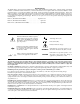
Caution STATIC-SENSITIVE DEVICE. Use anti-static procedures when removing, configuring, and installing a module. The Form C Switch is susceptible to static discharges. Do not install the Form C Switch without its metal shield attached. Connecting User Inputs The Form C Switch consists of a component module and a connector block. User inputs to the Form C Switch are to the NO, NC, and C terminal connectors on the terminal block. Figure 2-1 shows the connector block and associated channel numbers.
Figure 2-2.
Typical Switch Configurations Typical Form C Switch configurations are: • General purpose relay • Relay control • Digital output General Purpose Relay Configuration Example: General Purpose Relay Configuration As factory configured, the Form C Switch is set for general purpose relay configuration. For this configuration, you can switch channels by opening or closing channel relays or you can scan a set of channels. Figure 2-3 shows a typical general purpose relay configuration for channel 00.
Example: Relay Control Configuration Figure 2-4 shows one way to control external relays using the +5V/NO source. For this example, channel 15 is dedicated to provide the +5V source to external relays 1 and 2. When the Form C Switch channel 00 relay is open, external relay 1 is connected to ground and +5V is applied to external relay 1. When the Form C Switch channel 00 is closed, external relay 2 is connected to ground and +5V is applied to external relay 2. Figure 2-4.
Digital Output Configuration Note Example: Digital Output Configuration By connecting jumpers and installing pullup/pulldown resistors, you can configure the switch as a digital output device. When connecting the + 5V or + 12V backplane sources for digital output operation, you must install pullup resistors on the Form C Switch for the supplies used. Also, the total current drawn by user circuits should not exceed 1 A per Form C Switch for the + 5V supply or 0.5 A per Form C Switch for the + 12V supply.
Changing Form C Switch Components As required, you can: • Change the Logical Address switch setting • Change interrupt priority jumper positions • Replace fuses on the switch component module See Figure 2-6 for component locations. Figure 2-6.
Module Front Panel Connections If you choose not to use the supplied connector block, Figure 2-7 shows the E1364A front panel and the connection diagram for wiring your own terminal connector. Figure 2-7.
Chapter 3 Using the Agilent E1364A Form C Switch Using This Chapter This chapter provides examples to use the Form C Switch for switching channels and scanning channels. As required see Chapter 4, Understanding the Form C Switch, for further information on scanning channels. See Chapter 5, Form C Switch Command Reference, for command information. Chapter contents are: • Form C Switch Commands . . . . . . . . . . . . . . . . . . . . . . . . . . Page 25 • Switching Channels . . . . . . . . . . . . . . . . .
Switching Channels For general purpose relay operation, you can connect or disconnect a load by opening or closing specified channel relays. By adding jumpers and/or pullup/pulldown resistors, the switch can be configured for relay control or digital output operations. Use CLOS to connect a channel’s normally open (NO) terminal to its common (C) terminal or use OPEN to connect a channel’s normally closed (NC) contact to its common (C) terminal.
Example: Controlling Microwave Relays This example shows one way that the Form C Switch can be used to control an (external) microwave relay. Figure 3-2 shows an Agilent 33311B Microwave Relay connected to channel 00 of a Form C Switch. The + 5V source for the microwave relay is provided via channel 15 of the Form C Switch (via JM148, JM145, and the channel 15NO terminal). With this configuration, the Form C Switch provides a ground path for the coil current of the microwave relay.
Example: Controlling RF Switches/Step Attenuators Figure 3-3 shows one way to drive Agilent 8761 SPDT RF Switches or Agilent 33300 Series Programmable Step Attenuators. (Figure 3-3 only shows control for the Agilent 33300 40 dB step. Additional drive relays are required for the 10 dB and 20 dB steps.) The Agilent 8761A and Agilent 33300A/C operate from a 12-15V coil voltage, while the Agilent 8761B and Agilent 33300B/D operate from a 24V-30V coil voltage.
Example: Digital Output Configuration Figure 3-4 shows channel 00 configured for digital output operation. When the channel 00 relay is open (NC connected to C), point 1 is at + V and point 2 is at 0 V. When the channel 00 relay is closed (NO connected to C), points 1 and 2 are both at 0 V. (This configuration is useful for 24V or 48V control logic, since this type of application cannot be met with the configuration shown in Chapter 2, Figure 2-5.
Example: Matrix Switching The Form C Switch can be configured as a 4 x 4 single-wire matrix to connect any combination of up to four user sources (S0, S1, S2, and S3) to any combination of up to four user instruments (I0, I1, I2, and I3) at a time. Figure 3-5 shows a typical configuration. This example closes channel 02 to correct S2 to I0 and closes channel 13 to connect S1 to I3. To close channels 02 and 13, execute: CLOS (@102,113) Close channels 02 and 13.
Scanning Channels • For the Form C Switch, scanning channels consists of closing a specified set of channels, one channel at a time. You can scan any combination of channels for a single-module or a multiple-module switchbox. • Single, multiple, or continuous scanning modes are available. See Chapter 4 for information on scanning Form C Switch channels.
Figure 3-6. Example: Scanning Using Trig Out Port Scanning Channels Comments Channel List Can Extend Across Boundaries. For multiple-module switchbox instruments, the channels to be scanned can extend across switch modules. For example, for a two-module switchbox instrument, SCAN (@100:215) will scan all channels of both Form C Switches. Setting Multiple/Continuous Scans. Use ARM:COUNt to set from 1 to 32767 scans. Use INITiate:CONTinous ON to set continuous scanning. See Chapter 4 for details.
Chapter 4 Understanding the Agilent E1364A Form C Switch Using This Chapter This chapter describes some techniques to scan Form C switch channels and to use the Scan Complete bit. In addition, this chapter describes how the instrument responds to special 488.2 commands and the SCPI query, SYStem:ERRor? The chapter contents are: • • • • • • Scanning Channels Commands . . . . . . . . . . . . . . . . . . . . . . . Using Scanning Trigger Sources . . . . . . . . . . . . . . . . . . . . . .
Sets Number of Scanning Cycles ARM:COUN sets 1 to 32767 scanning cycles per INIT command. Selects the Trigger Source TRIG:SOUR defines the trigger source to advance the scan. Default is TRIG:SOUR IMM. TRIG:SOUR? queries the current trigger source. Sources are: BUS = *TRG via GPIB EXT = Event In Connector HOLD = Hold Triggering IMM = Automatic advance Selects Continuous Scanning Cycles Use INIT ON or INIT 1 to enable continuous cycles.
Trigger Hold (TRIG:SOUR HOLD) Immediate Triggering (TRIG:SOUR IMM) TRIG:SOUR HOLD prevents execution of triggers until trigger source is changed. Can use TRIG command to trigger a switchbox set to TRIG:SOUR HOLD. Advancing Scan (TRIG) Can use TRIG command to advance the scan list when switchbox is in TRIG:SOUR HOLD or TRIG:SOUR BUS. For either trigger source, the scan list advances on channel per TRIG command. TRIG:SOUR IMM sets immediate (internal) triggering. The scan list is automatically advanced.
Example: Scanning With External Devices This example uses the mainframe Trig Out port to synchronize the Form C Switch channel closures to an external measurement device. See the following figure for typical user connections. For measurement synchronization, the Agilent E1300B/E1301B Trig Out BNC port is connected to the instrument External Trigger In port. For this example, the mainframe and instrument are connected via GPIB with mainframe address of 709 and instrument address of 722.
Example: Scanning Using Trig Out and Event In Ports This example uses the mainframe Trig Out and Event In ports to synchronize Form C switch channel closures with an external measurement device. See the following figure for typical user connections. For this example, the mainframe and instrument are connected via GPIB with mainframe address of 709 and instrument address of 722. The Form C Switch logical address is 120 (secondary address = 120/8 = 15).
Using the Scan Complete Bit You can use the Scan Complete bit (bit 8) in the Operation Status Register of a switchbox to determine when a scanning cycle completes (no other bits in the register apply to the switchbox). Bit 8 has a decimal value of 256 and you can read it directly with the STAT:OPER? command. See the STATus:OPERation[:EVENt]? command in Chapter 5 for an example. When enabled by the STAT:OPER:ENAB 256 command, the Scan Complete bit will be reported as bit 7 of the Status Register.
Special 488.2 Commands This section contains information about the response of the switchbox instrument to three IEEE 488.2 common commands. Storing States The *SAV command saves the current instrument state. The state number (0-9) is specified by the parameter. The settings saved by this command are: • • • • • ARM:COUNt TRIGger:SOURce OUTput:STATe INITiate:CONTinuous SCAN (the scan list is set to invalid; therefore, the command does not save a scan list.
SCPI Error Responses The SYSTem:ERRor? query requests a value from the instrument’s error register. This register contains an integer in the range [-32768 to 327671]. The response takes the following form: , The is the value of the instrument’s error register. The is a short description of the error, followed by further information about the error. If no error occurs, the switchbox responds with 0,"No error".
Chapter 5 Agilent E1364A Form C Switch Command Reference Using This Chapter This chapter summarizes Standard Commands for Programmable Instruments (SCPI) and IEEE 488.2 Common (*) commands. See the Agilent 75000 Series B B-Size VXIbus Mainframe Agilent E1300B/E1301B User’s Manual or the Agilent 75000 Series C Agilent E1405A User’s Manual for additional information on SCPI and common commands. Chapter contents are: • • • • Command Types . . . . . . . . . . . . . . . . . . . . . . . . . . . . . . . . . .
Command Separator A colon (:) always separates one command from the next lower level command as shown below: ROUTe:SCAN:MODE? Colons separate the root command from the second-level command (ROUTe:SCAN) and the second level from the third-level (SCAN:MODE?). Abbreviated Commands The command syntax shows most commands as a mixture of upper- and lower-case letters. The upper case letters indicate the abbreviated spelling for the command. For shorter program lines, send the abbreviated form.
Parameters Parameter Types. The following table contains explanations and examples of the parameter types you might see later in this chapter. Table 5-1. SCPI Parameter Types Parameter Type Explanations and Examples Numeric Accepts all commonly used decimal representations of numbers including optional signs, decimal points, and scientific notation. 123, 123E2, -123,-1.23E2, .123, 1.23E-2, 1.23000E-01. Special cases include MIN, MAX and INF.
SCPI Command Reference This section describes the Standard Commands for Programmable Instruments (SCPI) commands for the Form C Switch. Commands are listed alphabetically by subsystem and also within each subsystem. ABORt The ABORt command subsystem stops a scan in progress when the scan is enabled via the interface and the trigger source is TRIGger:SOURce BUS or TRIGger:SOURce HOLD.
ARM The ARM subsystem selects the number of scanning cycles (1 to 32767) for each INITiate command. Subsystem Syntax :COUNt ARM :COUNt MIN | MAX :COUNt? [MIN | MAX] ARM:COUNt MIN | MAX allows scanning cycles to occur a multiple of times (1 to 32767) with one INITiate command when INITiate:CONTinuous OFF | 0 is set. MIN sets 1 cycle, MAX sets 32767 cycles.
:COUNt? ARM:COUNt? [MIN|MAX] returns the current number of scanning cycles set by ARM:COUNt. The current number of scan cycles is returned when MIN or MAX is not supplied. With MIN or MAX as a parameter, MIN returns 1 and MAX returns 32767.
DISPlay The DISPlay subsystem monitors the channel state of a selected module (or card) in a switchbox. This subsystem operates only with mainframes which have a display, such as the Agilent 75000 Series B mainframe (Agilent Model Number E130lB). Subsystem Syntax MONitor:CARD DISPlay :MONitor :CARD | AUTO [:STATe] DISPlay:MONitor CARD | AUTO selects the module in a switchbox to be monitored.
MONitor[:STATe] DISPlay:MONitor[:STATe] turns the monitor mode on or off. Parameters Comments Parameter Name Parameter Type Range of Values boolean ON l OFF | 1 | 0 • Monitoring Switchbox Channels: DISPlay:MONitor[:STATe] ON or DISPlay:MONitor[:STATe] 1 turns the monitor mode ON to show the channel state of the selected module. DISPlay:MONitor[:STATe] OFF or DISPlay:MONitor[:STATe] 0 turns the monitor mode OFF.
INITiate The INITiate command subsystem selects continuous scanning cycles and starts the scanning cycle. Subsystem Syntax :CONTinuous INITiate :CONTinuous :CONTinuous? [:IMMediate] INITiate:CONTinuous ON | OFF | 1 | 0 enables or disables continuous scanning cycles for the switchbox.
:CONTinuous? Example INITiate:CONTinuous? queries the scanning state. With continuous scanning enabled, the command returns 1. With continuous scanning disabled, the command returns 0. Query Continuous Scanning State: This example enables continuous scanning of a switchbox and queries the state. Since continuous scanning is enabled, INIT:CONT? returns 1.
OUTPut The OUTPut command subsystem enables or disables the "Trig Out" port of the Agilent E1300B/E130lB Mainframes or on the Agilent E1405/E1406 Command Modules. Subsystem Syntax [:STATe] OUTPut [:STATe] [:STATe]? OUTPut[:STATe] enables or disables the "Trig Out" BNC port on the rear panel of the Agilent E1300B/E1301B Mainframes or on the Agilent E1405/E1406 Command Modules. OUTPut[:STATe] ON | 1 enables the port and OUTPut[:STATe] OFF | 0 disables the port.
[ROUTe:] The ROUTe command subsystem controls switching and scanning operations for Form C Switch modules in a switchbox. Subsystem Syntax CLOSe [ROUTe:] CLOSe CLOSe? OPEN OPEN? SCAN :MODE NONE | VOLT :MODE? [ROUTe:]CLOSe closes the Form C Switch channels specified by channel_list. channel_list has the form (@ccnn) where cc = card number (01-99) and nn = channel number (00-15).
CLOSe? Comments [ROUTe:] CLOSe? returns the current state of the channel(s) queried. channel_list has the form (@ccnn) (see [ROUTe:]CLOSe for definition). The command returns 1 if channel(s) are closed or returns 0 if channel(s) are open. • Query is Software Readback: The [ROUTe:]CLOSe? command returns the current software state of the channel(s) specified. It does not account for relay hardware failures. A maximum of 127 channels at a time can be queried for a multi-module switchbox.
OPEN? [ROUTe:]OPEN? returns the current state of the channel(s) queried. channel_list has the form (@ccnn) (see [ROUTe:]OPEN for definition). The command returns 1 if channel(s) are open or returns 0 if channel(s) are closed. Comments • Query is Software Readback: The ROUTe:OPEN? command returns the current software state of the channels specified. It does not account for relay hardware failures. A maximum of 127 channels at a time can be queried for a multi-module switchbox.
SCAN:MODE [ROUTe:]SCAN:MODE NONE | VOLT can be used for the Form C Switch. Both NONE and VOLT set the mode for "no measurements". This command has no effect on Form C Switch operation. [ROUTe:] SCAN:MODE? can be used to query the scanning mode (NONE or VOLT) for the Form C Switch. STATus The STATus subsystem reports the bit values of a Standard Operation Status Register. It enables the Status Register to set a bit after a bit is set to 1 by the Operation Status Register.
:OPERation:ENABle STATus:OPERation:ENABle enables the Operation Status Register to set a bit in the Status Register. For the Form C Switch, when bit 8 in the Operation Status Register is set to 1, bit 7 in the Status Register is set to 1.
• Maximum Error Numbers/Messages in the Error Queue: The queue holds a maximum of 30 error numbers/messages for each switchbox. If the queue overflows, the last error number/message in the queue is replaced by -350, "Too many errors". The least recent error numbers/messages remain in the queue and the most recent are discarded.
:CPON SYSTem:CPON | ALL sets the selected module (card) in a switchbox to its power-on state. Parameters Comments Parameter Name Parameter Type Range of Values numeric 1 - 99 • Form C Switch Module Power-On State: The power-on state is all channels (relays) open. Note that *RST opens all channels of all modules in a switchbox, while SYSTem:CPON opens the channels in only the module (card) specified in the command.
Example :SOURce Advancing Scan Using TRIGger Command This example uses the TRIGger command to advance the scan of a single-module switchbox from channel 00 through 03. Since TRIGger:SOURce HOLD is set, the scan is advanced one channel each time TRIGger is executed.
• Using Bus Triggers: To trigger the switchbox with TRIGger:SOURce BUS selected, use the IEEE 488.2 common command *TRG or the GPIB Group Execute Trigger (GET) command. • Trig Out Port Shared by Switchboxes: See the OUTPut command. • Related Commands: ABORt, [ROUTe:]SCAN. • *RST Condition: TRIGger:SOURce IMMediate Examples Scanning Using External Triggers: This example uses external triggering (TRIG:SOUR EXT) to scan channels 00 through 03 of a single-module switchbox.
IEEE 488.2 Common Commands The following table lists the IEEE 488.2 Common (*) Commands that apply to the Form C Switch module. The operation of some of these commands is described in Chapter 4 of this manual. For more information on Common Commands, refer to the Agilent 75000 Series B Mainframe (Agilent Model Number E1300B/E1301B) User’s Manual or the ANSI/IEEE Standard 488.2-1987.
Command Quick Reference SCPI Commands Quick Reference Command Description ABORt Abort a scan in progress. ARM :COUNt :COUNt? [MIN | MAX] Multiple scans per INIT command. Query number of scans. DISPlay :MONitor:CARD | AUTO :MONitor[:STATe] Selects module to be monitored. Selects monitor mode. INITiate :CONTinuous :CONTinuous? [:IMMediate] Enables/disables continuous scanning. Query continuous scan state. Starts a scanning cycle.
Appendix A Agilent E1364A Form C Switch Specifications Maximum Input Voltage: C to NC or NO: 250VDC 250VAC RMS 354VAC Peak Any term. to chassis: 250VDC 250VAC RMS 354VAC Peak Maximum Current: Per switch: lA DC lA AC RMS Capacitance: C to NC or NO: <20pF Chan. to Chan.: <20pF Relay Life (typical): No load: >106 operations Max. load: >105 operations Power Up/Down States: all open / left in last state Maximum Power: Per switch: 40W DC 40VA AC Per module: 320W DC 320VA AC Terminals: screw type, max.
Relay Life Electromechanical relays are subject to normal wear-out. Relay life depends on several factors. The effects of loading and switching frequency are briefly discussed below: Relay Load. In general, higher power switching reduces relay life. In addition, capacitive/inductive loads and high inrush currents (e.g., turning on a lamp or starting a motor) reduce relay life. Exceeding specified maximum inputs can cause catastrophic failure. Switching Frequency. Relay contacts heat up when switched.
Appendix B Agilent E1364A Form C Switch Registers Register Definitions The Agilent E1364A Form C Switch is a register-based device. See Figure B-1 for register definitions.
Addressing the Registers To read or write to specific registers, you must use the register address. Since the addresses for Agilent 75000 Series B or Series C plug-in modules are A00 through A15, use the VME A16 mnemonic for the address space. The address space within the mainframe/command module memory map depends on the mainframe/command module used. For example, the address of the Agilent E1300B/E1301B Mainframe starts at lF000016.
Channel Enable Register A read of the Channel Enable register (base + 0816) always returns FFFF16, regardless of the channel states. Writing to the Registers You can write to the following Form C Switch registers: • Status/Control register (base + 0416) • Channel Enable register (base + 0816) The only write allowed to the Status/Control register (base + 0416) is to bit 0. Writing a "1" to bit 0 resets the switch (all channels open) You must then write a "0" to bit 0 to complete the reset.
68 Agilent E1364A Form C Switch Registers Appendix B
Appendix C Agilent E1364A Form C Switch Error Messages Table C-l lists the error messages associated with the Form C Switch module programmed by SCPI. See the appropriate mainframe manual for a complete list of error messages. Table C-1. Form C Switch Error Messages No. Title Potential Cause(s) -211 Trigger ignored Trigger received when scan not enabled. Trigger received after scan complete. Trigger too fast.
70 Agilent E1364A Form C Switch Error Messages Appendix C
Index Agilent E1364A 16 Channel Form C Switch ! *CLS 61 *ESE 61 *ESE? 61 *ESR? 61 *IDN? 61 *OPC 61 *OPC? 61 *RCL 61 *RST 61 *SAV 61 *SRE 61 *SRE? 61 *STB? 61 *TRG 61 *TST? 61 *WAI 61 +12 Volts 13, 22 +12V Jumpers 20 +5 V Jumpers 20 +5 Volts 13, 22 488.
E Enable Scanning 34 End of Relay Life 64 :ERRor 56 Error Messages 69 - 70 Error Responses 40 Event In Port 37 Example Controlling Microwave Relays 27 Controlling RF Switches/Step Attenuators 28 Digital Output Configuration 29 Matrix Switching 30 Scan Complete Interrupt 38 Scanning Using Trig Out and Event In Ports 37 Scanning Using Trig Out Port 31 Scanning with External Instruments 36 Voltage Switching 26 External Instruments 33, 36 F Field Wiring 18 Form C Switch Description 11 Front Panel 24 Fuses 23
Relay Replacement Strategy 64 Relays, Form C 12 RF Switches 28 [ROUT:]CLOS 25 [ROUT:]CLOS? 25 [ROUT:]OPEN 25 [ROUT:]SCAN 25 [ROUTe:] Subsystem 52 [ROUTe:]CLOSe 52 [ROUTe:]CLOSe? 53 [ROUTe:]OPEN 53 [ROUTe:]OPEN? 54 [ROUTe:]SCAN 54 [ROUTe:]SCAN:MODE 55 S Safety warnings 6 *SAV 39 SCAN 54 Scan Complete Bit 38 Scan Cycles 34 Scan Mode 34 Scan, Stopping 44 SCAN:MODE 55 Scanning Channels 31, 33 Scanning using Trig Out Port 31 Scanning with External Instruments 33, 36 Schematic 12 SCPI command Format 41 SCPI Erro
74 Agilent E1364A 16 Channel Form C Switch Index