
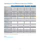
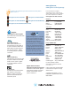
Specifications

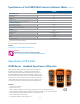

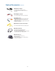

Built-in pulse signal generator for calibrating fl ow meter systems
Flow meters output pulses with frequen-
cies that are proportional to the rate of
fl ow of liquid that passes through its bladed
turbine rotor. These pulses are then fed
to a signal conditioner. Calibration of
the signal conditioner requires injecting
known pulse signals into it and checking
that the resulting output is what it should be.
Right on site and with the U1401B in
hand, you can conveniently simulate the
fl ow meter’s output pulses into the signal
conditioner, without needing a separate
function generator.
U1401B
calibrator/meter simulates
electrical signal generated
by the fl ow meter
Adjustable
frequency,
amplitude, duty
cycle and
pulse width
Signal conditioner converts frequency input
to the equivalent 4-20 mA current output
Pulses are fed to the
signal conditioner
Magnetic pickup coil
generates electrical pulses
Rotation in
proportion to
rate of fl ow
Liquid
fl o w
Turbine
flow
meter
Flow tube
Bladed turbine rotor
4-20 mA
Signal
conditioner
U1401B
Display
Dual display Yes
Counts 50,000
Backlight Yes
Source
Voltage ± 15 V
Current ± 25 mA
Square-wave 0.5 Hz to 4.8 kHz, selectable Hz and %
Auto scan and ramp Yes
Simultaneous operation with MEASURE function Yes
Measure
True RMS AC+DC
Basic DCV accuracy 0.03% + 5 counts
Auto/Manual ranging Yes
Voltage AC/DC 250 V
Current AC/DC 500 mA
Resistance 50 MΩ
Frequency
200 kHz
Temperature 1372 °C, K-type thermocouple
Continuity with beeper Yes
Diode test Yes
4-20 mA, 0 to 20 mA % scale Yes
Simultaneous operation with SOURCE function Yes
represents key specifi cations/features
Specifications of the U1401B Multi-function Calibrator/Meter
31