Agilent U1270 Series Handheld Digital Multimeters Service Guide Agilent Technologies
Notices © Agilent Technologies, Inc. 2010–2014 Warranty No part of this manual may be reproduced in any form or by any means (including electronic storage and retrieval or translation into a foreign language) without prior agreement and written consent from Agilent Technologies, Inc. as governed by United States and international copyright laws. The material contained in this document is provided “as is,” and is subject to change, without notice, in future editions.
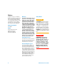
Safety Symbols The following symbols on the instrument and in the documentation indicate precautions which must be taken to maintain safe operation of the instrument.
Safety Considerations Read the information below before using this multimeter. The descriptions and instructions in this manual apply to the Agilent U1271A, U1272A, U1273A, and U1273AX Handheld Digital Multimeters (hereafter referred to as the multimeter). The U1273A and U1272A models appear in all illustrations. CAUTION • Disconnect circuit power and discharge all high-voltage capacitors before measuring resistance, continuity, diodes, or capacitance.
WA R N I N G • Do not apply more than the rated voltage (as marked on the multimeter) between terminals, or between the terminal and earth ground. Before use, verify the multimeter's operation by measuring a known voltage. • Never use the multimeter in wet conditions or when there is water on the surface. If the multimeter is wet, ensure that the multimeter is dried only by trained personnel. • When measuring current, turn off the circuit power before connecting the multimeter in the circuit.
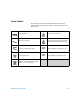
Environmental Conditions This instrument is designed for indoor use and in an area with low condensation. The table below shows the general environmental requirements for this instrument.
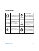
Regulatory Markings The CE mark is a registered trademark of the European Community. This CE mark shows that the product complies with all the relevant European Legal Directives. The C-tick mark is a registered trademark of the Spectrum Management Agency of Australia. This signifies compliance with the Australia EMC Framework regulations under the terms of the Radio Communication Act of 1992. ICES/NMB-001 indicates that this ISM device complies with the Canadian ICES-001.
Waste Electrical and Electronic Equipment (WEEE) Directive 2002/96/EC This instrument complies with the WEEE Directive (2002/96/EC) marking requirement. This affixed product label indicates that you must not discard this electrical or electronic product in domestic household waste. Product Category: With reference to the equipment types in the WEEE directive Annex 1, this instrument is classified as a “Monitoring and Control Instrument” product. The affixed product label is as shown below.
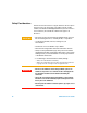
Declaration of Conformity (DoC) The Declaration of Conformity (DoC) for this instrument is available on the Agilent Web site. You can search the DoC by its product model or description at the Web address below. http://regulations.corporate.agilent.com/DoC/search.htm NOTE U1270 Series Service Guide If you are unable to search for the respective DoC, please contact your local Agilent representative.
THIS PAGE HAS BEEN INTENTIONALLY LEFT BLANK.
Table of Contents 1 Calibration Procedures Calibration Overview 18 Closed-case calibration 18 Agilent calibration services 18 Calibration interval 19 Adjustment is recommended 19 Recommended Test Equipment 20 Basic Operating Test 22 Backlight test (U1271A/U1272A only) Display test 22 Current terminal input test 23 Calibration Process 25 Test Considerations 26 Performance Verification Tests Calibration Security 22 27 37 Unsecuring the Instrument for Calibration 38 To unsecure the instrument from t
2 Service and Maintenance Troubleshooting 52 Checking the Fuse 53 Fuse Replacement 57 Returning the Instrument for Service Replaceable Parts 62 To order replaceable parts 61 62 Types of Service Available 63 Extended service contracts 63 Obtaining Repair Service (Worldwide) XII 64 U1270 Series Service Guide
List of Figures Figure 1-1 Figure 1-2 Figure 1-3 Figure 1-4 Figure 1-5 Figure 1-6 Figure 1-7 Figure 1-8 Figure 2-1 Figure 2-2 Figure 2-3 Figure 2-4 Figure 2-5 U1270 Series Service Guide U1273A/U1273AX OLED display screen U1271A/U1272A LCD screen 23 Input warning display (A terminal) 23 Input warning display (µA mA terminal) Unsecuring the instrument 38 Changing the calibration security code Resetting the calibration security code Reference value display 47 Testing Fuse 1 55 Testing Fuse 2 56 Replacing Fus
THIS PAGE HAS BEEN INTENTIONALLY LEFT BLANK.
List of Tables Table 1-1 Table 1-2 Table 1-3 Table 1-4 Table 2-1 Table 2-2 U1270 Series Service Guide Recommended test equipment 20 Performance verification tests 28 Adjustment input values 43 Calibration error codes 50 Operating checklist 52 Fuse displayed readings 54 XV
THIS PAGE HAS BEEN INTENTIONALLY LEFT BLANK.
U1270 Series Handheld Digital Multimeters Service Guide 1 Calibration Procedures Calibration Overview 18 Closed-case calibration 18 Agilent calibration services 18 Calibration interval 19 Adjustment is recommended 19 Recommended Test Equipment 20 Basic Operating Test 22 Backlight test (U1271A/U1272A only) 22 Display test 22 Current terminal input test 23 Calibration Process 25 Test Considerations 26 Performance Verification Tests 27 Calibration Security 37 Unsecuring the Instrument for Calibration 38 To un
1 Calibration Procedures Calibration Overview Calibration Overview This manual contains procedures to verify the U1270 Series handheld digital multimeters performance and to perform adjustments (calibration). The performance test procedures allow you to verify that the instrument is operating within its published specifications. The adjustment procedures ensure that the instrument remains within its specifications until the next calibration.
Calibration Procedures Calibration Overview 1 Calibration interval A 1- year interval is adequate for most applications. Accuracy specifications are warranted only if adjustment is made at regular calibration intervals. Accuracy specifications are not warranted beyond the 1- year calibration interval. Agilent does not recommend extending calibration intervals beyond 2 years for any application. Adjustment is recommended Specifications are only guaranteed within the period stated from the last adjustment.
1 Calibration Procedures Recommended Test Equipment Recommended Test Equipment The test equipment recommended for the performance verification and adjustment procedures are listed below (Table 1- 1). If the exact instrument is not available, substitute with another calibration standard of equivalent accuracy. A suggested alternative method is to use the Agilent 3458A 8½ Digit Digital Multimeter to measure less accurate but stable sources.
Calibration Procedures Recommended Test Equipment 1 Table 1-1 Recommended test equipment (continued) Application Temperature U1270 Series Service Guide Recommended Recommended accuracy requirements equipment Fluke 5520A <20% of the U1270 Series accuracy specification Short Shorting plug — a dual banana plug with a copper wire shorting the two terminals Zlow Agilent U1252B — 21
1 Calibration Procedures Basic Operating Test Basic Operating Test The tests listed below are used to test the basic operability of the instrument. Repair is required if the instrument fails any of these tests. • “Backlight test (U1271A/U1272A only)” • “Display test” • “Current terminal input test” Backlight test (U1271A/U1272A only) Press and hold the key while turning the rotary switch to any other position (OFF to ON). Check that the multimeter’s backlight is turned on.
Calibration Procedures Basic Operating Test 1 For U1271A/U1272A models: Check that all the annunciators are displayed on the LCD screen. Compare the display with the example shown in Figure 1- 2. Press any key to exit this mode. Figure 1-2 U1271A/U1272A LCD screen Current terminal input test This test determines if the input warnings of the current terminals are functioning properly.
1 Calibration Procedures Basic Operating Test The alert beep tone will continue to beep until the test lead is removed from the A terminal or until the rotary switch is set to the function. NOTE Before conducting this test, ensure that the beep function is not disabled in the multimeter’s setup. Input warning test (µA mA terminal) The multimeter sounds a continuous alert beep when the test lead is inserted into the µA mA terminal but the rotary switch is not set to the or function.
Calibration Procedures Calibration Process 1 Calibration Process 1 Prior to performing the verification tests, see the “Test Considerations” on page 26. 2 Perform the verification tests to characterize the instrument; see “Performance Verification Tests” on page 27. 3 Unsecure the instrument for calibration; see “Calibration Security” on page 37. 4 Prior to performing the adjustments, see the “Adjustment considerations” on page 42. 5 Perform the adjustment procedure; see “Adjustment procedure” on page 47.
1 Calibration Procedures Test Considerations Test Considerations For optimum performance, all procedures should comply with the following recommendations: • The performance verification test or adjustment should be performed under laboratory conditions where the ambient temperature can be controlled. • The instrument should be put under the laboratory environment for at least 1 hour. • Ensure that the calibration ambient temperature is stable and is between 18 °C and 28 °C.
Calibration Procedures Performance Verification Tests 1 Performance Verification Tests Use the performance verification tests to verify the measurement performance of the instrument. The performance verification tests use the instrument's specifications listed in the U1271A/U1272A User's Guide and the U1273A/U1273AX User’s Guide (available for download at www.agilent.com/find/hhTechLib). The performance verification tests are recommended as acceptance tests when you first receive the instrument.
1 Calibration Procedures Performance Verification Tests Table 1-2 Performance verification tests Step Test function 1[1] Range Qik-V Turn the rotary switch to the Qik-V position. 1000 V ZLOW 1000 V Turn the rotary switch to the Z position. 5520 output Error from nominal 1 year U1271A U1272A/ U1273A/U1273AX 1000 V ±20 V - 1000 V, 70 Hz ±250 V - 3V - ±2.
Calibration Procedures Performance Verification Tests 1 Table 1-2 Performance verification tests (continued) Step Test function 2 ACV Turn the rotary switch to the position. Range 3V 30 V 300 V 1000 V U1270 Series Service Guide 5520 output Error from nominal 1 year U1271A U1272A/ U1273A/U1273AX 3 V, 20 Hz - ±0.0325 V 3 V, 45 Hz ±0.0230 V ±0.0200 V 3 V, 65 Hz ±0.0230 V ±0.0200 V 3 V, 1 kHz ±0.0325 V ±0.0325 V 3 V, 5 kHz ±0.0625 V ±0.0475 V 3 V, 20 kHz ±0.0640 V ±0.0640 V 2.
1 Calibration Procedures Performance Verification Tests Table 1-2 Performance verification tests (continued) Step Test function Range LPF While the rotary switch is in the position, press the key once. Frequency While the rotary switch is in the position, press the key once. Error from nominal 1 year U1271A U1272A/ U1273A/U1273AX 3 V, 20 Hz - ±0.0325 V 3 V, 45 Hz ±0.0230 V ±0.0200 V 3 V, 65 Hz ±0.0230 V ±0.0200 V 2.7 V, 430 Hz ±0.1375 V ±0.1375 V 9.9999 kHz 1.0000 kHz, 0.096 V ±0.
Calibration Procedures Performance Verification Tests 1 Table 1-2 Performance verification tests (continued) Step Test function 6 7 Range DCV Turn the rotary switch to the / position. AC+DCV switch to the press the Turn the rotary position, and key twice. Error from nominal 1 year U1271A U1272A/ U1273A/U1273AX 3V 3V ±0.0020 V ±0.0020 V 30 V 30 V ±0.017 V ±0.017 V 300 V 300 V ±0.17 V ±0.17 V 1000 V 1000 V ±0.7 V ±0.7 V 3V 3 V, 20 Hz - ±0.0360 V 3 V, 45 Hz - ±0.
1 Calibration Procedures Performance Verification Tests Table 1-2 Performance verification tests (continued) Step Test function AC+DCV switch to the press the Range Turn the rotary position, and key twice. 1000 V Shift Esc View 8 DCmV[2] Turn the rotary switch to the / position. 30 mV 300 mV 5520 output Error from nominal 1 year U1271A U1272A/ U1273A/U1273AX 1000 V, 45 Hz - ±9.5 V 1000 V, 65 Hz - ±9.5 V 1000 V, 1 kHz - ±14.0 V 1000 V, 5 kHz - ±19.0 V 30 mV - ±0.
Calibration Procedures Performance Verification Tests 1 Table 1-2 Performance verification tests (continued) Step Test function Range AC+DCmV Turn the rotary switch to the position, and press the key twice. 10 300 mV Shift Esc View Resistance Turn the rotary switch to the Smart / position. 5520 output Error from nominal 1 year U1271A U1272A/ U1273A/U1273AX 300 mV, 20 Hz - ±2.70 mV 300 mV, 45 Hz - ±2.35 mV 300 mV, 65 Hz - ±2.35 mV 300 mV, 1 kHz - ±2.70 mV 300 mV, 5 kHz - ±3.
1 Calibration Procedures Performance Verification Tests Table 1-2 Performance verification tests (continued) Step Test function 12 Capacitance[6] Range Turn the rotary switch to the position. 5520 output Error from nominal 1 year U1271A U1272A/ U1273A/U1273AX 10 nF 10 nF ±0.015 nF ±0.015 nF 100 nF 100 nF ±1.02 nF ±1.02 nF 1000 nF 1000 nF ±10.2 nF ±10.2 nF 10 μF 10 μF ±0.102 μF ±0.102 μF 100 μF 100 μF ±1.02 μF ±1.02 μF 1000 μF 1000 μF ±10.2 μF ±10.2 μF 10 mF 10 mF ±0.
Calibration Procedures Performance Verification Tests 1 Table 1-2 Performance verification tests (continued) Step Test function 15 ACμA While the rotary Range U1272A/ U1273A/U1273AX 300 μA, 20 Hz - ±2.95 μA 300 μA, 45 Hz ±2.95 μA ±2.05 μA 300 μA, 65 Hz ±2.95 μA ±2.05 μA 300 μA, 1 kHz ±2.95 μA ±2.95 μA 3000 μA, 20 Hz - ±29.5 μA 3000 μA, 45 Hz ±29.5 μA ±20.5 μA 3000 μA, 65 Hz ±29.5 μA ±20.5 μA 3000 μA, 1 kHz ±29.5 μA ±29.5 μA 30 mA 30 mA ±0.065 mA ±0.
1 Calibration Procedures Performance Verification Tests Table 1-2 Performance verification tests (continued) Step Test function 19 ACA While the rotary switch is in the position, press the key once. Range 3A Shift Esc View 10 A 36 5520 output Error from nominal 1 year U1271A U1272A/ U1273A/U1273AX 3 A, 45 Hz ±0.0325 A ±0.0265 A 3 A, 65 Hz ±0.0325 A ±0.0265 A 3 A, 1 kHz ±0.0325 A ±0.0325 A 10 A, 45 Hz ±0.125 A ±0.105 A 10 A, 65 Hz ±0.125 A ±0.105 A 10 A, 1 kHz ±0.125 A ±0.
Calibration Procedures Calibration Security 1 Calibration Security The calibration security code prevents accidental or unauthorized adjustments to the instrument. When you first receive your instrument, it is secured. Before you can adjust the instrument, you must unsecure it by entering the correct security code (see “Unsecuring the Instrument for Calibration” on page 38). NOTE The security code can only be changed after the instrument has been unsecured.
1 Calibration Procedures Unsecuring the Instrument for Calibration Unsecuring the Instrument for Calibration Before you can adjust the instrument, you must unsecure it by entering the correct security code. The default security code is set to 1234. NOTE If you forget your security code, see “To reset the calibration security code to its factory default” on page 40. To unsecure the instrument from the front panel 1 Power- on the instrument and press the and keys simultaneously for more than 1 second.
Calibration Procedures Unsecuring the Instrument for Calibration 1 If the correct security code is entered, PASS is shown briefly, after which the instrument will enter the adjustment mode. If the incorrect security code is entered, an error code will appear briefly, after which the instrument will prompt you for the security code again. To change the calibration security code 1 After the instrument has been unsecured, press more than 1 second.
1 Calibration Procedures Unsecuring the Instrument for Calibration To reset the calibration security code to its factory default If you have forgotten the correct calibration security code, you may follow the steps below to reset the calibration security code to the factory default code (1234). NOTE If you do not have a record (or have lost the record) of the security code, first try the factory default code, “1234”.
Calibration Procedures Unsecuring the Instrument for Calibration 1 If the four digits entered are correct, the display will show PASS. The calibration security code is now set to its factory default code, 1234. If the incorrect security code is entered, an error code will appear briefly, after which the instrument will prompt you for the security code again. If you want to enter a new security code, see “To change the calibration security code” on page 39.
1 Calibration Procedures Using the Front Panel for Adjustments Using the Front Panel for Adjustments This section describes the procedures to perform adjustments from the front panel. To unsecure the instrument, see “To unsecure the instrument from the front panel” on page 38. Once unsecured, the reference value will be indicated on the display. Adjustment considerations NOTE After each adjustment, the display shows PASS.
Calibration Procedures Using the Front Panel for Adjustments 1 Valid adjustment input values Adjustment can be accomplished using the following input values below. Table 1-3 Adjustment input values Test function DCmV Step Reference value Valid reference input SHORT SHORT SHORT V/COM terminals 30 mV 30.000 mV 0.9 to 1.1 × Reference value 300 mV 300.00 mV 0.9 to 1.1 × Reference value 3.000 mV (70 Hz) 0.9 to 1.1 × Reference value 30.000 mV (70 Hz) 0.9 to 1.1 × Reference value 30.
1 Calibration Procedures Using the Front Panel for Adjustments Table 1-3 Adjustment input values (continued) Test function Step Reference value Valid reference input 0.3000 V (70 Hz) 0.9 to 1.1 × Reference value 3.0000 V (70 Hz) 0.9 to 1.1 × Reference value 3.0000 V(3 kHz) 0.9 to 1.1 × Reference value 3.000 V (70 Hz) 0.9 to 1.1 × Reference value 30.000 V (70 Hz) 0.9 to 1.1 × Reference value 30.000 V(3 kHz) 0.9 to 1.1 × Reference value 30.00 V (70 Hz) 0.9 to 1.1 × Reference value 300.
Calibration Procedures Using the Front Panel for Adjustments 1 Table 1-3 Adjustment input values (continued) Test function Step Reference value Valid reference input 03.000 mA (70 Hz) 0.9 to 1.1 × Reference value 30.000 mA (70 Hz) 0.9 to 1.1 × Reference value 030.00 mA (70 Hz) 0.9 to 1.1 × Reference value 300.00 mA (70 Hz) 0.9 to 1.1 × Reference value 0.3000 A (70 Hz) 0.9 to 1.1 × Reference value 3.0000 A (70 Hz) 0.9 to 1.1 × Reference value 3.0000 A (70 Hz) 0.9 to 1.
1 Calibration Procedures Using the Front Panel for Adjustments Table 1-3 Adjustment input values (continued) Test function Step Reference value Valid reference input SHORT 0 Ω[2] 0 Ω from calibrator OPEN OPEN terminals 10.000 MΩ 0.9 to 1.1 × Reference value 3 MΩ 3.0000 MΩ 0.9 to 1.1 × Reference value 300 kΩ 300.00 kΩ 0.9 to 1.1 × Reference value 30 kΩ 30.000 kΩ[2] 0.9 to 1.1 × Reference value 3 kΩ 3.0000 kΩ[2] 0.9 to 1.1 × Reference value 300 Ω 300.00 Ω[2] 0.9 to 1.
Calibration Procedures Using the Front Panel for Adjustments 1 Adjustment procedure NOTE Review the “Test Considerations” and “Adjustment considerations” before beginning the adjustment procedures. 1 Turn the rotary switch to the respective test function position as shown in the adjustment input values table (Table 1- 3). 2 Unsecure the instrument to enter the adjustment mode. (See “Unsecuring the Instrument for Calibration” on page 38).
1 Calibration Procedures Using the Front Panel for Adjustments NOTE You are highly recommended to complete the adjustments in the same order as shown in Table 1-3. 7 Use the arrow keys to enter the actual applied input values. Hz % ms Log 8 Press to start the adjustment. CAL is shown on the display to indicate that the calibration is in progress. 9 Upon completion of each adjustment value, the display will show PASS.
Calibration Procedures Calibration Count 1 Calibration Count You can query the instrument to determine how many adjustments have been performed. NOTE The instrument has been calibrated before it left the factory. You are recommended to record the initial value of the calibration count once you receive the instrument. The count value increases by one for each calibration point, from 0000 up to the maximum of 19999. After the maximum count, the calibration count will reset to 0.
1 Calibration Procedures Calibration Error Codes Calibration Error Codes The following errors indicate failures that may occur during a calibration.
U1270 Series Handheld Digital Multimeters Service Guide 2 Service and Maintenance Troubleshooting 52 Checking the Fuse 53 Fuse Replacement 57 Returning the Instrument for Service 61 Replaceable Parts 62 To order replaceable parts 62 Types of Service Available 63 Extended service contracts 63 Obtaining Repair Service (Worldwide) 64 This chapter will help you troubleshoot a failing instrument. It also describes how to obtain repair services and lists the replaceable assemblies.
2 Service and Maintenance Troubleshooting Troubleshooting WA R N I N G To avoid electrical shock, do not perform any servicing unless you are qualified to do so. CAUTION Any repair or service which is not covered in this manual should only be performed by qualified personnel. If the instrument fails to operate, check the batteries and the test leads. Replace them if necessary. If the instrument still does not function, check the operating procedures in this manual.
Service and Maintenance Checking the Fuse 2 Checking the Fuse It is recommended that you check the fuse(s) of the multimeter before using it. Follow the instructions below to test the fuses inside the multimeter. NOTE Refer to Figure 2-5 for the respective positions of Fuse 1 (10 × 35 mm, 440 mA/1000 V fast-acting fuse) and Fuse 2 (10 × 38 mm, 11 A/1000 V fast-acting fuse). 1 Turn the rotary switch to the Smart or position and connect the red test lead to the Ω input terminal.
2 Service and Maintenance Checking the Fuse Table 2-2 Fuse displayed readings Displayed readings Current input terminal 54 Fuse Part number Fuse rating Fuse healthy Replace fuse 1 2110-1400 440 mA/1000 V ≈102 Ω OL 2 2110-1402 11 A/1000 V ≈0.
Service and Maintenance Checking the Fuse Smart 2 Smart Figure 2-1 Testing Fuse 1 U1270 Series Service Guide 55
2 Service and Maintenance Checking the Fuse Smart Smart Figure 2-2 Testing Fuse 2 56 U1270 Series Service Guide
Service and Maintenance Fuse Replacement 2 Fuse Replacement NOTE No recalibration is required after replacing the fuse. The current input terminals of your multimeter are fuse protected. The fuses are located next to the battery compartment. • The µA mA terminal is protected by a 10 × 35 mm 440 mA/1000 V 30 kA fast- acting fuse (Fuse 1). • The A terminal is protected by a 10 × 38 mm 11 A/1000 V 30 kA fast- acting fuse (Fuse 2).
2 Service and Maintenance Fuse Replacement 1 2 3 Figure 2-3 Replacing Fuse 1 58 U1270 Series Service Guide
Service and Maintenance Fuse Replacement 2 1 2 3 Figure 2-4 Replacing Fuse 2 U1270 Series Service Guide 59
2 Service and Maintenance Fuse Replacement Fuse 1: 10 × 35 mm 440 mA/1000 V fast-acting fuse Fuse 2: 10 × 38 mm 11 A/1000 V fast-acting fuse Figure 2-5 Positions of Fuse 1 and Fuse 2 60 U1270 Series Service Guide
Service and Maintenance Returning the Instrument for Service 2 Returning the Instrument for Service Before shipping your instrument for repair or replacement, Agilent recommends that you acquire the shipping instructions from the Agilent Service Center. A clear understanding of the shipping instructions is necessary to secure your product for shipment.
2 Service and Maintenance Replaceable Parts Replaceable Parts This section contains information for ordering replacement parts for your instrument. You can find the instrument support parts list at Agilent's Test & Measurement Parts Catalog: http://www.agilent.com/find/parts The parts lists include a brief description of each part with its corresponding Agilent part number. To order replaceable parts You can order replaceable parts from Agilent using the Agilent part number.
Service and Maintenance Types of Service Available 2 Types of Service Available If your instrument fails during the warranty period, Agilent will repair or replace it under the terms of your warranty. After your warranty expires, Agilent offers repair services at competitive prices. Extended service contracts Many Agilent products are available with optional service contracts that extend the covered period after the standard warranty expires.
2 Service and Maintenance Obtaining Repair Service (Worldwide) Obtaining Repair Service (Worldwide) To obtain service for your instrument (in- warranty, under service contract, or post- warranty), contact your nearest Agilent Service Center. They will arrange to have your unit repaired or replaced, and can provide warranty or repair- cost information where applicable.
www.agilent.