
Technical data


1 Calibration Procedures
Performance Verification Tests
34 U1270 Series Service Guide
12
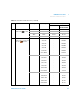
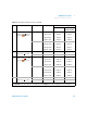
Capacitance
[6]
Tur n the
rotary switch to the
position.
10 nF 10 nF ±0.015 nF ±0.015 nF
100 nF 100 nF ±1.02 nF ±1.02 nF
1000 nF 1000 nF ±10.2 nF ±10.2 nF
10 μF10 μF ±0.102 μF ±0.102 μF
100 μF100 μF ±1.02 μF ±1.02 μF
1000 μF 1000 μF±10.2 μF±10.2 μF
10 mF 10 mF ±0.102 mF ±0.102 mF
[6] The accuracy for all ranges is specified based on a film capacitor or better, and after the Null function is used to subtract
the residual values (by opening the test leads).
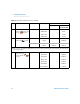
13
Tem pe ra tu re
[7]
While
the rotary switch is in the
position, press the key
once.
–200 °C to 1372 °C –200 °C ±3.0 °C ±3.0 °C
0 °C ±1.0 °C ±1.0 °C
1372 °C ±14.7 °C ±14.7 °C
[7] Ensure that the ambient temperature is stable within ±1 ºC. Ensure that the multimeter is placed in a controlled
environment for at least 1 hour before you proceed to ensure that the multimeter’s internal reference junction sensor and
input terminal are stabilized at the same environment. Keep the multimeter away from any ventilation exit.
Differences in ambient compensation between the calibrator and multimeter may cause some deviations shown between
the readings of the calibrator and multimeter. Placing the multimeter close to the output terminal of the calibrator will help
reduce this deviation.
Keep the thermocouple test lead as close to the multimeter as possible.
Do not touch the thermocouple test lead after connecting it to the calibrator. Allow the connection to stabilize for at least
another 15 minutes before performing the measurement.
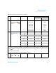
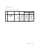
14
DCμA Turn the rotary
switch to the position.
300 μA300 μA ±0.65 μA ±0.65 μA
3000 μA 3000 μA ±6.5 μA ±6.5 μA
Table 1 - 2 Performance verification tests (continued)
Step Test function Range 5520 output Error from nominal 1 year
U1271A U1272A/
U1273A/U1273AX
S
h
i
f
t
V
i
e
w
E
s
c