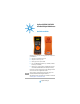
Agilent U1273A/U1273AX Handheld Digital Multimeter Quick Start Guide Verify that you received the following items in the shipment of your multimeter: ✔ One pair of red and black test leads ✔ One pair of 4 mm test probes ✔ One K-type thermocouple lead kit ✔ Four 1.
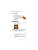
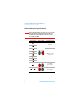
U1273A/U1273AX Handheld Digital Multimeter Install the Batteries Install the Batteries Your multimeter is powered by four 1.5 V AAA batteries (included with the shipment). 1 Turn the rotary switch to OFF and remove the test leads from the terminals. 2 Lift the tilt stand and loosen the screws with a suitable Phillips screwdriver. 3 Remove the battery cover and observe the polarity markings. 4 Insert the batteries and replace the battery cover and screws.
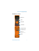
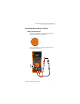
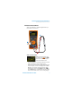
U1273A/U1273AX Handheld Digital Multimeter The Multimeter at a Glance The Multimeter at a Glance Display screen Keypad Rotary switch Input terminals Test lead/probe holders IR communication port Battery cover (Lift tilt stand for access) Tilt stand U1273A/U1273AX Quick Start Guide 3
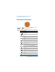
U1273A/U1273AX Handheld Digital Multimeter Understanding the Rotary Switch Understanding the Rotary Switch NO TE Press to switch between the primary and shifted functions shown on the rotary switch.
U1273A/U1273AX Handheld Digital Multimeter Understanding the Keypad Understanding the Keypad Legend Key response when pressed for: Less than 1 second More than 1 second Sets the Null/Relative mode. Sets the Scale mode for the specified ratio and unit display. Starts the MaxMin recording. Starts and stops the Peak recording. Freezes the present reading in the display. Automatically freezes the present reading once the reading is stable. Switches between available dual-combination displays.
U1273A/U1273AX Handheld Digital Multimeter Understanding the Input Terminals Understanding the Input Terminals WA RN ING Ensure that the terminal connections are correct for that particular measurement function before starting any measurement. To avoid damage to the device, do not exceed the input limit. Rotary position Input terminals Overload protection 1000 Vrms ZLOW 1000 Vrms for short circuit <0.
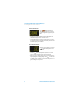
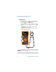
U1273A/U1273AX Handheld Digital Multimeter Performing Measurements and Tests Performing Measurements and Tests Voltage measurements The figure below highlights the primary functions allowing voltage measurements in your multimeter. Set up your multimeter as shown in the figure below to perform voltage measurements.
U1273A/U1273AX Handheld Digital Multimeter Performing Measurements and Tests LPF measurements: Shift Esc View Press while performing ac voltage measurements to pass the measured signal through a low pass filter. • Passing the measured signal through a LPF help blocks unwanted voltages such as electronic noise. • Use the LPF function to improve measurement on composite sine waves that are typically generated by inverters and variable frequency motor drives.
U1273A/U1273AX Handheld Digital Multimeter Performing Measurements and Tests Resistance measurements Set up your multimeter as shown in the figure below to perform resistance measurements. 4 3 2 Smart 1 Smart Ω measurements: While performing resistance measurements, press until BiAS is shown on the secondary display to enable the Smart Ω function. Shift Esc View • Use the Smart Ω (offset compensation) function to measure resistors affected by dc offset or leakage current.
U1273A/U1273AX Handheld Digital Multimeter Performing Measurements and Tests Continuity tests Set up your multimeter as shown in the figure below to perform continuity tests. Press to switch to the continuity test function ( is shown on the display). Shift Esc View The beeper will sound as a continuity indication. Press switch between normal open ( ) and normal close ( contacts. Dual Exit to ) • Normal open: Circuit is normally open, the beeper will sound when a short is detected.
U1273A/U1273AX Handheld Digital Multimeter Performing Measurements and Tests Diode tests Set up your multimeter as shown in the figure below to perform diode tests. 4 3 2 Auto 1 Auto-diode tests: Press function. Shift Esc View to use the auto diode • The Auto-diode function tests both the forward bias and reverse bias directions of your diode simultaneously. The forward bias voltage is shown on the primary display and the reverse bias voltage is shown on the secondary display.
U1273A/U1273AX Handheld Digital Multimeter Performing Measurements and Tests Capacitance measurements Set up your multimeter as shown in the figure below to perform capacitance measurements. 4 3 2 1 NO TE 12 is shown on the bottom left of the display when the capacitor is charging, and is shown when the capacitor is discharging.
U1273A/U1273AX Handheld Digital Multimeter Performing Measurements and Tests Temperature measurements Set up your multimeter as shown in the figure below to perform temperature measurements. Press to switch to the temperature measurement function. Shift Esc View WA RN ING Do not connect the thermocouple to electrically live circuits. Doing so will potentially cause fire or electric shock.
U1273A/U1273AX Handheld Digital Multimeter Performing Measurements and Tests Current measurements Set up your multimeter as shown in the figure below to perform current measurements. Press to switch between ac, dc, ac+dc, or % scale current measurements. Shift Esc View WA RN ING Always use the proper function, range, and terminals for current measurements. Set the positive input terminal to the terminal for currents below 440 mA, and the terminal for currents above 440 mA.
U1273A/U1273AX Handheld Digital Multimeter Check the Fuse Check the Fuse Follow the instructions below for a quick check on the fuses (Fuse 1 and Fuse 2) of your multimeter. Fuse Part number Displayed readings Fuse rating Fuse healthy Replace fuse 1 2110-1400 440 mA/1000 V ≈102 Ω OL 2 2110-1402 ≈0.
U1273A/U1273AX Handheld Digital Multimeter Check the Fuse NO TE 16 • To check Fuse 1: Ensure that the probe tip is touching the top half metal contact inside the µA mA terminal. • To check Fuse 2: Ensure that the probe tip is touching the left half metal contact inside the A terminal. The multimeter will sound an input warning alert if the probe tip is in contact with any other sides of the µA mA or A terminal other than the sides specified in the instructions above.
Contacting Agilent To obtain service, warranty, or technical assistance, contact us at the following phone numbers: • United States Call Center: 800-829-4444 • Canada Call Center: 877-894-4414 • China Call Center: 800-810-0189 • Europe Call Center: 31-20-547-2111 • Japan Call Center: (81) 426-56-7832 For other countries, contact your country’s Agilent support organization. A list of contact information for other countries is available on the Agilent Web site: www.agilent.
Printed in Malaysia U1273-90004 First Edition, August 5, 2012 © Agilent Technologies, Inc.