Agilent U8001A/U8002A Single Output DC Power Supplies User’s and Service Guide Agilent Technologies
Notices © Agilent Technologies, Inc. 2008–2013 Warranty No part of this manual may be reproduced in any form or by any means (including electronic storage and retrieval or translation into a foreign language) without prior agreement and written consent from Agilent Technologies, Inc. as governed by United States and international copyright laws. The material contained in this document is provided “as is,” and is subject to being changed, without notice, in future editions.
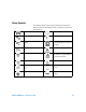
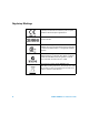
Safety Symbols The following symbols on the instrument and in the documentation indicate precautions which must be taken to maintain safe operation of the instrument. Direct current Off (supply) Alternating current On (supply) Both direct and alternating current Equipment protected throughout by double insulation or reinforced insulation. Three-phase alternating current Caution, risk of electric shock.
General Safety Information The following general safety precautions must be observed during all phases of operation, service and repair of this instrument. Failure to comply with these precautions or specific warnings elsewhere in this manual violates safety standards of design, manufacture and intended use of the instrument. Agilent Technologies assumes no liability for customer’s failure to comply with these requirements.
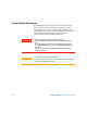
Environment Conditions This instrument is designed for indoor use in an installation category II, pollution degree 2 area. Table 1 shows general environment requirements.
Regulatory Markings The CE mark is a registered trademark of the European Community. This CE mark shows that the product complies with all the relevant European Legal Directives. ICES/NMB-001 indicates that this ISM device complies with Canadian ICES-001. The CSA mark is a registered trademark of the Canadian Standards Association. A CSA mark indicates that the product is certified for Canadian markets, to the applicable Canadian standards.
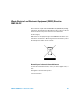
Waste Electrical and Electronic Equipment (WEEE) Directive 2002/96/EC This instrument complies with the WEEE Directive (2002/96/EC) marking requirement. This affixed product label indicates that you must not discard this electrical/electronic product in domestic household waste. Product Category: With reference to the equipment types in the WEEE directive Annex 1, this instrument is classified as a “Monitoring and Control Instrument” product.
Declaration of Conformity (DoC) The Declaration of Conformity (DoC) for this instrument is available on the Web site. You can search the DoC by its product model or description. http://regulations.corporate.agilent.com/DoC/search.htm NOTE VIII If you are unable to search for the respective DoC, please contact your local Agilent representative.
In This Guide… This guide provides step- by- step set up and configuration instructions that get you familiarized with the operations of the Agilent U8001A/U8002A single output DC power supplies. This guide also contains service information and troubleshooting guidelines that help to resolve your problems during startup configurations.
calibration procedures for your power supply, related documentation, and Agilent contacts.
Contents Chapter 1 Quick Start Preliminary Checkout 18 Output Checkout 19 Voltage Output Checkout 19 Current Output Checkout 20 If the Power Supply Does Not Turn On 21 To Rack-mount the Instrument 22 Chapter 2 General Information Front Panel at a Glance 24 Rear Panel at a Glance 25 Display Annunciators 26 Description 27 Installation 29 Initial inspection 29 Cooling and location 30 Output Connections 31 Voltage drops 31 Chapter 3 Operations and Features Constant Voltage Operation 34 Constant Current Operatio
Contents Recalling Operating State 39 Programming Over Voltage Protection 40 Programming Over Current Protection 42 Keylock Operation 44 Backlight Operation 45 System Related Operations 46 Reset to factory defaults 46 Power-on self-test 46 Extending the Voltage and Current Range 47 Series connection 47 Parallel connection 47 Chapter 4 Specifications and Characteristics Performance Specifications 50 Supplemental Characteristics 51 Chapter 5 Service Guide Equipment Warranty 56 Replacement Parts 58 Troublesho
Contents U8001A/U8002A User’s and Service Guide 15
Contents 16 U8001A/U8002A User’s and Service Guide
Agilent U8001A/U8002A Sinlge Output DC Power Supplies User’s and Service Guide 1 Quick Start Preliminary Checkout 18 Output Checkout 19 If the Power Supply Does Not Turn On 21 To Rack-mount the Instrument 22 This chapter is intended for both the experienced and inexperienced users because it calls attention to certain checks that should be made prior to operation.
1 Quick Start Preliminary Checkout The following steps help you to validate that the power supply is ready for use. 1 Check the list of supplied item. Verify that you have received the following items together with your power supply. If anything is found missing, contact your nearest Agilent Technologies Sales Office. • Power cord • Certificate of Calibration • Product Reference CD- ROM 2 Connect the power cord and turn on the power supply.
Quick Start 1 Output Checkout The following procedures check to ensure that the power supply develops its rated outputs and properly responds to operation from the front panel. For complete performance and verification tests, refer to the “Service Guide”. NOTE If an error has been detected during the output checkout procedures, the ERROR annunciator will be turned on. See “Appendix A: List of Error Codes” for more information.
1 Quick Start Current Output Checkout The following steps check basic current functions with a short across the power supply's output. 1 Turn on the power supply. Make sure that the output is disabled. The OFF annunciator is on. 2 Connect a short across (+) and (–) output terminals with an insulated test lead. Use a wire size sufficient to handle the maximum current (refer to the American Wire Gauge standard). 3 Enable the output.
Quick Start 1 If the Power Supply Does Not Turn On Use the following steps to help solve problems you might encounter when turning on the instrument. If you need more help, refer to Chapter 5 for instructions on returning the instrument to Agilent Technologies for service. 1 Verify that there is ac power to the power supply. First, verify that the power cord is firmly plugged into the power receptacle on the rear panel of the power supply.
1 Quick Start To Rack-mount the Instrument You can mount the power supply in a standard 19- inch rack cabinet using one of three optional kits available. Instructions and mounting hardware are included with each rack- mounting kit. To rack- mount a single instrument, order adapter kit 5063- 9240. To rack- mount two instruments side- by- side, order lock- link kit, 5061- 9694 and flange kit, 5063- 9212. Be sure to use the support rails inside the rack cabinet.
Agilent U8001A/U8002A Single Output DC Power Supplies User’s and Service Guide 2 General Information Front Panel at a Glance 24 Rear Panel at a Glance 25 Display Annunciators 26 Description 27 Installation 29 Output Connections 31 This chapter provides general description of the instrument, front panel overview, rear panel overview, display annunciators and installation guidelines for U8001A/U8002A single output DC power supplies.
2 General Information Front Panel at a Glance 2 3 1 6 8 7 9 4 11 10 10 5 12 24 13 Panels Functions 1 LCD Display Displays the measurements. 2 Memory To set the memory settings, enables memory recall and memory state selection (M1, M2, M3). 3 CAL Enables voltage and current calibration. 4 Back Light To turn On/Off the backlight. 5 Lock / Unlock Enables and disables the front panel operation.
General Information 2 Rear Panel at a Glance 1 4 5 2 Panels Functions 1 AC inlet Connects AC power line. 2 Power fuse-holder assembly Sets the line voltage to the proper values for different country based. 3 Power-line module Combination of the AC inlet and power fuse-holder assembly. 4 Physical lock mechanism Enables physical lock mechanism. 5 Line Voltage Fuse Rating indicator Indicates the line voltage and line fuse rating.
2 General Information Display Annunciators Over voltage Protection Over current Protection LOCK Limit Memory State 3 Memory State 2 Memory State 1 OFF Constant Voltage Constant Current Annunciators Functions M1 Stores states of power supply in non-volatile memory M2 When the power supply is in calibration mode, it can be used to store calibration constant.
General Information 2 Description The Agilent U8001A/U8002A single output DC power supplies are compact, general purpose bench supplies that are suitable for either bench or rack- mounted operations. These power supplies feature linear power supply performance and capable usabilities, making them ideal for power systems applications.
2 General Information The front- panel liquid crystal display (LCD) includes: • Displaying actual values of output voltage and current (meter mode) • Or displaying the limit values of voltage and current (limit mode) • Checking the operating status from the annunciators Front panel binding posts are available to connect load wires for bench operation. WA R N I N G 28 Floating the power supply output more than ±240 Vdc from the chassis presents an electric shock hazard to the operator.
General Information 2 Installation Initial inspection When you receive your power supply, inspect it for any obvious damage that may have occurred during shipment. If any damage is found, notify the carrier and the nearest Agilent Technologies Sales Office immediately. Warranty information is shown in the front of this manual. Keep the original packing materials in case the power supply has to be returned to Agilent Technologies in the future.
2 General Information Cooling and location Cooling The power supply can operate at rated specifications within the temperature range of 0 °C to 40 °C. Power supply loading is derated from 40 °C to 55 °C. A fan cools the power supply by drawing air through the sides and exhausting it out the back. Using an Agilent rack- mount will not impede the flow of air.
General Information 2 Output Connections WA R N I N G Before attempting to connect wires to the front output terminals, make sure to turn off the power supply first to avoid damage to the circuits being connected. Voltage drops The load wires must be large enough to avoid excessive voltage drops due to the impedance of the wires. In general, if the wires are heavy enough to carry the maximum short circuit current without overheating, excessive voltage drops will not be a problem.
2 32 General Information U8001A/U8002A User’s and Service Guide
Agilent U8001A/U8002A Single Output DC Power Supplies User’s and Service Guide 3 Operations and Features Constant Voltage Operation 34 Constant Current Operation 36 Memory Operations 38 Programming Over Voltage Protection 40 Programming Over Current Protection 42 Keylock Operation 44 Backlight Operation 45 System Related Operations 46 Extending the Voltage and Current Range 47 You have now learned how to install the power supply.
3 Operations and Features Constant Voltage Operation The following steps show you how to perform the constant voltage (CV) operation. 1 Turn on the power supply. • Press on the “Power” button to turn on the power supply. The power supply will then perform a self- test (Self- test is not indicated at display). • The display turns on all segments and shows the firmware version briefly after that. • The output is disabled by default. • The OFF annunciator turns on.
Operations and Features 3 4 Adjust for the desired current limit. • Press on the “Voltage/Current” button. When seeing the current value, “A” blinks, turn the knob to adjust for the desired current limit value. 5 Return to the meter mode. • Press on the “Display Limit” button to return to the meter mode. The LIMIT annunciator will be turned off. 6 Enable the output. • Press on the “Output On/Off” button to enable the output. • The OFF annunciator turns off and CV annunciator turns on.
3 Operations and Features Constant Current Operation The following steps show you how to perform the constant current operation. 1 Short the binding posts. • Press on the “Power” button to turn off the power supply. • Connect a short circuit between the positive (+) and negative (—) binding posts. 2 Turn on the power supply. • Press on the “Power” button to turn on the power supply. The power supply will then perform a self- test.
Operations and Features 3 5 Adjust for the desired output current. • Press on the “Voltage/Current” button. When seeing the current value, “A” blinks, turn the knob to adjust for the desired output current value. 6 Return to the meter mode. • Press on the “Display Limit” button to return to the meter mode. The LIMIT annunciator will be turned off. 7 Enable the output. • Press on the “Output On/Off” button to enable the output.
3 Operations and Features Memory Operations For Agilent U8001A/U8002A single output DC power supplies, up to three operating states can be stored in non- volatile storage locations. The storage feature remembers the voltage and current limit value settings, OVP*/OCP† On/Off states, and OVP/OCP trip levels. The following steps show you how to store and recall an operating state. Storing Operating State 1 Press on the “Memory” button. • The M1 annunciator will blink.
Operations and Features 3 Recalling Operating State 1 Press and hold the “Memory” button. • The M1 annunciator will be turned on. • The LIMIT annunciator will be turned off. • The display shows the settings saved in M1 memory location. 2 Turn the knob to show the settings saved in M1, M2 and M3 memory locations. • The M1, M2 and M3 annunciators will be turned on in round- robin manner.
3 Operations and Features Programming Over Voltage Protection Over voltage protection guards the load against output voltages reaching values greater than the programmed protection level. The following steps show how to enable and disable the over voltage protection (OVP), how to set the OVP trip level and how to clear the over voltage condition. To set the OVP trip level and enable OVP 1 Press on the “Over Voltage” button. • The LIMIT annunciator will be turned off.
Operations and Features 3 To disable OVP 1 Press on the “Over Voltage” button to disable the OVP. The OVP annunciator will eventually turn off. To clear the over voltage condition 1 OVP trip can only occur when the output is enabled. When the OVP condition occurs: • The output is disabled and the OFF annunciator will be turned on. • If the keylock feature was enabled, it will be disabled. The LOCK annuciator will be turned off. • The OVP annunciator will fast- blink continuously.
3 Operations and Features Programming Over Current Protection Over current protection guards the load against output currents reaching values greater than the programmed protection level. The following steps show how to enable and disable the over current protection (OCP), how to set the OCP trip level and how to clear the over voltage condition. To set the OCP trip level and enable OCP 1 Press on the “Over Current” button. • The LIMIT annunciator will be turned off.
Operations and Features 3 To disable the OCP 1 Press on the “Over Current” button to disable the OCP. The OCP annunciator will eventually turn off. To clear the over current condition 1 OCP trip can only occur when the output is enabled. When the OCP condition occurs: • The output is disabled and the OFF annunciator will be turned on. • If the keylock feature was enabled, it will be disabled. The LOCK annuciator will be turned off. • The OCP annunciator will fast- blink continuously.
3 Operations and Features Keylock Operation This operation provides locking function for the knob and all the buttons on front panel of the equipment which allows end users to secure their desired settings. The keylock is disabled by default when power- up. To enable keylock 1 Press on the “Lock/Unlock” button. The LOCK annunciator will be turned on. 2 When the keylock function is enabled, the knob and all the buttons are disabled EXCEPT “Lock/Unlock” button.
Operations and Features 3 Backlight Operation This operation provides the backlight for the LCD display. The backlight will be enabled by default when power- up. To turn on the backlight 1 Press on the “Back Light” button. The backlight will be turned on. To turn off the backlight 1 Press on the “Back Light” button. The backlight will be turned off.
3 Operations and Features System Related Operations Reset to factory defaults To reset the power supply unit to factory defaults, press and hold “Output On/Off” button when power- up. • The OVP and OCP are turned off and their values are set to maximum. • The memory storage locations are cleared • The voltage and current limit values are set to zero. • The calibration values are intact. Power-on self-test A power- on self- test occurs automatically when the power supply unit is turned on.
Operations and Features 3 Extending the Voltage and Current Range Two or more power supplies can be connected in series or parallel to extend the range of voltage and current. This may serve as a lower cost alternative to a power supply with higher power rating. Series connection Serial connection of two or more power supplies can achieve the output isolation rating of any one supply to obtain a higher voltage than a single power supply.
3 Operations and Features power supply should be set to a slightly higher output voltage. The power supply with higher output voltage setting will deliver its constant current output and drop its output voltage. This will happen until the output voltage equals the output of the other supply, and the other supply will remain in constant voltage operation; only delivering that fraction of rated output current that is necessary to fulfill the total load demand.
Agilent U8001A/U8002A Single Output DC Power Supplies User’s and Service Guide 4 Specifications and Characteristics Performance Specifications 50 Supplemental Characteristics 51 This chapter lists the power supply’s performance specifications and the supplemental characteristics of the equipment.
4 Specifications and Characteristics Performance Specifications Table 4-1 Electrical Specifications Parameter Output Ratings (at 0 °C to 40 °C) Line and Load Regulation U8001A U8002A 0 to +30 V 0 to +30 V 0 to 3 A 0 to 5 A CV: <0.01% +2 mV CC: <0.02% +2 mA Ripple and Noise (25 °C ±5 °C) CV: 12 mVp-p, <1 mVrms; CC: 3 mArms Load Transient Response Time <50 µs (within 15 mV from full load to half load and from half load to full load) Programming Accuracy* (25 °C ±5 °C) <0.35% +20 mV <0.
Specifications and Characteristics 4 Supplemental Characteristics Table 4-2 Supplemental Characteristics Parameter U8001A U8002A Temperature Coefficient (for 12 months) CV: <100 ppm/ °C CC: <380 ppm/ °C Output Voltage Overshoot CC: <300 ppm/ °C <1 V (during turn- on or turn- off AC power state with the output control set to less than 1 V) Voltage Programming Speed, to within 1% of total excursion Up Down Full Load 150 ms No Load 100 ms Full Load 30 ms No Load 450 ms Last Memory Setting En
4 Specifications and Characteristics Table 4-4 AC Power Input Specifications Parameter U8001A U8002A 100 Vac ± 10%,, 47 to 63 Hz Input Power Option (Selectable) 115 Vac ± 10%,, 47 to 63 Hz 230 Vac ± 10%,, 47 to 63 Hz Maximum Input Power 330 VA 500 VA Fuse External, customer assessable Table 4-5 Physical Specifications Parameter U8001A Dimension (H x W x L) Weight (kg) 52 U8002A 88.1 mm x 212.3 mm x 361.8 mm 7.3 kg 8.
Specifications and Characteristics 4 Figure 4-1 Physical dimensions of unit – length Figure 4-2 Physical dimensions of unit – width U8001A/U8002A User’s and Service Guide 53
4 Specifications and Characteristics Figure 4-3 Physical dimensions of unit – miscallaneous dimensions Figure 4-4 Physical dimensions of unit – height 54 U8001A/U8002A User’s and Service Guide
Agilent U8001A/U8002A Single Output DC Power Supplies User’s and Service Guide 5 Service Guide Equipment Warranty 56 Replacement Parts 58 Troubleshooting 59 Performance Verification and Calibration 63 Voltage Calibration 82 Current Calibration 84 This chapter contains service information for the U8001A/U8002A single output DC power supplies, including warranty information, general diassemble, verification steps to troubleshoot the connectivity and functionality, detailed calibration procedures for your po
5 Service Guide Equipment Warranty Types of Service Available If your instrument fails during the warranty period, Agilent Technologies will replace it under the terms of your warranty. After your warranty expires, Agilent offers repair by unit exchange service at competitive prices. Extended Service Contracts Many Agilent products are available with optional service contracts that extend the covered period after the standard warranty expires.
Service Guide 5 Before shipping your instrument, ask the Agilent Technologies Service Center to provide shipping instructions, including what components to ship. Agilent recommends that you retain the original shipping carton for use in such shipments. Repackaging for Shipment If the unit is to be shipped to Agilent for service or repair, be sure to: • Attach a tag to the unit identifying the owner and indicating the required service or repair. Include the model number and full serial number.
5 Service Guide Replacement Parts This section contains information for ordering replacement parts for your instrument. The parts lists are divided into the following sections. • Parts are listed in alphanumeric order according to their reference designators • The parts lists include a brief description of each part with applicable Agilent part number. To Order Replaceable Parts You can order replaceable parts from Agilent using the Agilent part number.
Service Guide 5 Troubleshooting This section provides a brief check list of common failures. Before troubleshooting or repairing the power supply, make sure that the failure is in the instrument rather than any external connections. Also make sure that the instrument is accurately calibrated. Unit is Inoperative • Verify that the AC power cord is connected to the power supply. • Verify that the front- panel power switch is at "ON" position. • Verify the power- line voltage setting.
5 Service Guide Line Voltage Conversion WA R N I N G Shock Hazard. Operating personnel must not remove power supply covers. Component replacement and internal adjustment must be made only by qualified service personnel. Line voltage conversion is accomplished by adjusting two components: the line voltage selection switch and the power- line fuse on the rear panel.
Service Guide 5 Orientation of the Voltage Selector AC Inlet 100 V 115 V 100 indication needs to be in this orientation 115 indication needs to be in this orientation 230 V 230 indication needs to be in this orientation Figure 5-6 Orientation of voltage selector AC inlet in different voltage selection U8001A/U8002A User’s and Service Guide 61
5 Service Guide Line Voltage Fuse Rating indicator for U8001A NOTE Line Voltage Fuse Rating indicator for U8002A The authorised personnel will mark the fuse rating indicator printed on the rear panel each time the fuse is changed. Self-Test Procedures Power-On Self-Test Each time the power supply is powered on, a set of self- tests are performed. These tests check that the minimum set of logic and measurement hardware are functioning properly.
Service Guide 5 Performance Verification and Calibration This chapter contains performance verification and calibration procedures. The performance verification procedures allow you to verify that the power supply is operating within its published specifications. The calibration procedures show how to make voltage and current adjustment on the power supply.
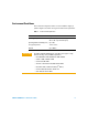
5 Service Guide Recommended Test Equipment The test equipment recommended for the calibration and adjustment is listed below. If the exact instrument is not available, substitute the calibration standards of equivalent requirement(s). Table 5-7 List of Equipment Equipment Requirement(s) Digital Multimeter (DMM) PV* Agilent DSO8064A or Infiniium equivalent Displays transient response. Displays ripple and noise waveform.
Service Guide 5 Table 5-7 List of Equipment Equipment Requirement(s) Resistive Load (RL) • 10 Ω/90 W (for U8001A) • 6 Ω/150 W (for U8002A) Current Monitoring Resistor (Shunt) (RM) • 0.01 Ω ± 0.1% • TCR less than 20 ppm/ºC Recommended Model Purpose ISOTEK Co.
5 Service Guide Measurement Techniques Test Setup Most tests are performed at the front terminals as shown below. Measure the DC voltage directly at the positive (+) and negative (–) terminals on the front panel.
Service Guide 5 Current Monitoring Resistor To eliminate output current measurement error caused by the voltage drops in the leads and connections, connect the current monitoring resistor (RM) between the (–) output terminal and the load as a four- terminal device. Connect the current monitoring leads inside the load- lead connections directly at the monitoring points on the resistor element.
5 Service Guide Electronic Load Many of the test procedures require the use of a variable load resistor capable of dissipating the required power. Using a variable load resistor requires that switches should be used to connect, disconnect, and short the load resistor. An electronic load, if available, can be used in place of a variable load resistor and switches. The electronic load is considerably easier to use than load resistors.
Service Guide 5 Constant Voltage (CV) Verification Voltage Programming and Readback Accuracy This test is to verify that the voltage programming and readback accuracy are within published specifications. Procedures: 1 Power off the power supply and connect a DMM between the (+) and (–) terminals of the output to be tested. Remove the electronic load or resistor block as shown in Figure 5- 7 (A), to operate as an open circuit. 2 Power on the power supply.
5 Service Guide CV Load Effect (Load Regulation) This test measures the change in the output voltage resulting from a change in the output current from full load to no load or vice versa. Procedures: 1 Power off the power supply and connect a DMM between the (+) and (–) terminals of the output as shown in Figure 5- 7(A). 2 Power on the power supply. 3 When the power supply is in limit mode, program the output voltage to full rated value, i.e. 30 V and output current to the maximum programmable value.
Service Guide 5 CV Source Effect (Line Regulation) This test measures the change in output voltage that results from a change in AC line voltage from the minimum value to maximum value. Procedures: 1 Power- off the power supply and connect a DMM between the (+) and (–) terminals of the output to be tested as shown in Figure 5- 7(A). 2 Connect the AC power line through an AC voltage source. Adjust the AC voltage source to provide nominal input voltage to the power supply. 3 Power on the power supply.
5 Service Guide CV Noise CV noise is specified as the RMS or peak- to- peak output voltage in the frequency range from 20 Hz to 20 MHz. Procedures: 1 Power off the power supply and connect the output to be tested as shown in Figure 5- 7(C) to a differential amplifier and load resistor (10 Ω for U8001A and 6 Ω for U8002A) 2 Power on the power supply. 3 When the display is in the limit mode, program the output voltage to full rated value, i.e. 30 V and output current to the maximum programmable value.
Service Guide 5 • Enable Auto- triggering 8 Allow the scope run for a few seconds to generate enough measurement points. 9 Obtain the maximum peak- to- peak voltage measurement as indicated in the scope. Divide this value by 10 to get the CV peak- to- peak noise measurement. The result should not exceed 12 mVpp. 10 Configure the RMS voltmeter as below: • Set high pass filter to10 Hz • AC coupling 11 Disconnect the oscilloscope and connect an RMS voltmeter in its place.
5 Service Guide Load Transient Response Time This test measures the time for the output voltage to recover to within 15 mV of nominal output voltage following a load change from full load to half load or vice versa. Procedures: 1 Power off the power supply and connect the output to be tested as shown in Figure 5- 7(A) with an oscilloscope. Operate the electronic load in constant current mode. 2 Power on the power supply.
Service Guide 5 Figure 5-9 Graph of load transient response U8001A/U8002A User’s and Service Guide 75
5 Service Guide Constant Current (CC) Verification Current Programming and Readback Accuracy This test is to verify that the current programming and readback accuracy are within published specifications. The accuracy of the current monitoring resistor must be 0.1% or better. Procedures: 1 Power- off the power supply and connect a 0.01 Ω current shunt monitoring resistor (RM) across the output to be tested and a DMM across the current monitoring resistor (RM). 2 Power on the power supply.
Service Guide 5 12 Divide the voltage drop (DMM reading) across the current monitoring resistor (RM) by its resistance to convert to amps and record this value (IO). This value should be within the limit of: • U8001A: 3 A ±30.5 mA • U8002A: 5 A ±37.5 mA 13 When the power supply is in meter mode, record the current reading displayed on the front display of the power supply. This value should be within the limit of: • U8001A: IO ±30.5 mA • U8002A: IO ±37.
5 Service Guide CC Load Effect (Load Regulation) This test measures the immediate change in output current resulting from a change in the load from full rated output voltage to short circuit. Procedures: 1 Power off the power supply and connect the output to be tested as shown in Figure 5- 7(B) with the DMM connected across the 0.01 Ω current monitoring resistor (RM). 2 Power on the power supply.
Service Guide 5 CC Source Effect (Line Regulation) This test measures the change in output current that results from a change in AC line voltage from the minimum value to the maximum value. Procedures: 1 Power off the power supply and connect the output to be tested as shown in Figure 5- 7(B) with the DMM connected across the current monitoring resistor (RM). 2 Connect the AC power line through an AC voltage source. Adjust the AC voltage source to provide nominal input voltage to the power supply.
5 Service Guide 9 Compare the reading obtained in steps 7 and 8. The difference should be within the limit of: • U8001A: 2.
Service Guide 5 CC Noise CC noise is specified as the RMS output current in a frequency range 20 Hz to 20 MHz with the power supply in constant current operation. Procedures: 1 Power off the power supply and connect the output to be tested as shown in Figure 5- 7(D) to an AC/DC converter and load resistor (10 Ω for U8001A and 6 Ω for U8002A). 2 Power on the power supply.
5 Service Guide Voltage Calibration Before attempting to calibrate the power supply, please ensure that you have disconnected all loads from the power supply and connect a digital voltmeter (DVM) across the output terminals. You will be calibrating for low voltage, middle voltage and high voltage point respectively. Make sure that the power supply is in constant voltage (CV) mode along the voltage calibration. 1 Enter calibration mode.
Service Guide 5 4 High Voltage Calibration Point. • Display will show "C" blinking. • The M3 annunciator will be turned on. • Use the knob to enter the reading obtained from the DVM. • Press the "Memory" button to save the changes voltage calibration is done. You will be able to perform this if the power supply is in CV mode. 5 Voltage Calibration • Display will show "donE” for a few seconds and the power supply will enter the current calibration mode.
5 Service Guide Current Calibration For current calibration, connect an appropriate shunt 0.01 Ω across the output terminals, and connect a digital voltmeter (DVM) across the shunt resistor. Same as voltage calibration, you will also be calibrating for low current, middle current and high current calibration point respectively. Make sure that the power supply is in constant current (CC) mode along the current calibration. 1 Current Calibration mode • Display will show "C" blinking.
Service Guide 5 3 Middle current calibration point. • Display will show "C" blinking. • The M2 annunciator will be turned on. • Use the knob to enter the computed value (DVM reading divided by shunt resistance). • Press the "Memory" button to save the changes and move to the next calibration point. You will be able to perform this if the power supply is in CC mode. 4 High current calibration point. • Display will show "C" blinking. • The M3 annunciator will be turned on.
5 86 Service Guide U8001A/U8002A User’s and Service Guide
Agilent U8001A/U8002A Single Output DC Power Supplies User’s and Service Guide Appendix Appendix A: List of Error Codes 58 Agilent Technologies 57
Appendix Appendix A: List of Error Codes The following table contains the list of error codes and the interpretations for each code.
www.agilent.