
Technical data
74 U8001A/U8002A User’s and Service Guide
5Service Guide
Load Transient Response Time
This test measures the time for the output voltage to recover
to within 15 mV of nominal output voltage following a load
change from full load to half load or vice versa.
Procedures:
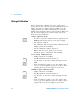
1 Power off the power supply and connect the output to be
tested as shown in Figure 5- 7(A) with an oscilloscope.
Operate the electronic load in constant current mode.
2 Power on the power supply.
3 When the display is in the limit mode, program the
output voltage to full rated value, i.e. 30 V and output
current to the maximum programmable value.
4 Enable the output.
5 Set the electronic load to transient operation mode
between one half of the output's full rated value and the
output’s full rated value at a 1 kHz rate with 50% duty
cycle.
6 Set the oscilloscope coupling, internal sync and lock on
either the positive or negative load transient.
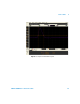
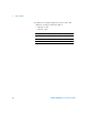
7 Adjust the oscilloscope to display transients as shown in
Figure 5- 9. Note that the pulse width (t2–t1) of the
transients at 15 mV from the base line is no more than 50
µs for the output.