OPERATING GUIDE for SOLAR ARRAY SIMULATOR AGILENT MODELS E4350B, E4351B Agilent Model E4350B: US37410101 and Above * Agilent Model E4351B: US37430101 and Above * * For instruments with higher Serial Numbers, a change page may be included. Agilent Part No.
CERTIFICATION Agilent Technologies Company certifies that this product met its published specifications at time of shipment from the factory. Agilent Technologies further certifies that its calibration measurements are traceable to the United States National Bureau of Standards, to the extent allowed by the Bureau’s calibration facility, and to the calibration facilities of other International Standards Organization members.
SAFETY SUMMARY The following general safety precautions must be observed during all phases of operation, service, and repair of this instrument. Failure to comply with these precautions or with specific warnings elsewhere in this manual violates safety standards of design, manufacture, and intended use of the instrument. Agilent Technologies Company assumes no liability for the customer’s failure to comply with these requirements. BEFORE APPLYING POWER.
SAFETY SUMMARY (continued) GENERAL Any LEDs used in this product are Class 1 LEDs as per IEC 825-l. ENVIRONMENTAL CONDITIONS All instruments are intended for indoor use in an installation category II, pollution degree 2 environment. They are designed to operate at a maximum relative humidity of 95% and at altitudes of up to 2000 meters. Refer to the specifications tables for the ac mains voltage requirements and ambient operating temperature range.
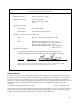
DECLARATION OF CONFORMITY according to ISO/IEC Guide 22 and EN 45014 Manufacturer’s Name: Agilent Technologies Company Manufacturer’s Address: 150 Green Pond Road Rockaway, New Jersey 07866 U.S.A.
Table Of Contents 1 General Information What’s In This Guide? ..................................................................................................................................13 Safety Considerations....................................................................................................................................13 Options and Accessories................................................................................................................................
Capacitive Loads .....................................................................................................................................30 Inductive Loads ......................................................................................................................................31 Connecting to an External Voltage Source..............................................................................................31 Sense Connections....................................................
Types of SCPI Messages ..............................................................................................................................51 The Message Unit....................................................................................................................................52 Headers....................................................................................................................................................52 Query Indicator ...................................
Measure Subsystem .......................................................................................................................................72 MEAS:CURR? ........................................................................................................................................72 MEAS:VOLT? ........................................................................................................................................72 Memory Subsystem .......................................
8. Status Reporting Agilent SAS Status Structure.........................................................................................................................87 Operation Status Group .................................................................................................................................87 Register Functions ...................................................................................................................................87 Register Commands..............
Entering the Calibration Values ............................................................................................................109 Saving the Calibration Constants...........................................................................................................109 Disabling the Calibration Mode ............................................................................................................109 Changing the Calibration Password.................................................
1 General Information What’s In This Guide? This guide describes the Agilent Model E4350B/E4351B Solar Array Simulator (SAS). An overview of the unit is given in this chapter. Installation and user connections are discussed in chapters 2 and 4. Programming from the front panel and over the GPIB is discussed in chapters 5-7. If you just need to check that the unit is operating properly, read chapter 3. The edition and current revision of this manual are indicated on the title page.
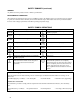
Operator Replaceable Parts Description Cover, dc output Foot, cabinet Fuse, power 100 Vac line voltage, 15 A 120 Vac line voltage, 12 A 220/230/240 Vac line voltage, 7 A Knob, rotary output control Table 1-3 Operator Replaceable Parts Agilent Part No. Description 0360-2191 Plug, analog connector 5041-8801 Plug, digital connector Screw, output bus bar Screw, terminal cover 2110-0054 Screw, carrying strap, M5x0.8x10 mm 2110-0249 Standoff, GPIB 21l0-06l4 0370-3238 Agilent Part No.
Output Characteristic The Agilent E4350B/E4351B Solar Array Simulator can be operated in three modes: fixed mode, simulator mode, and table mode. Mode switching on the Agilent SAS is accomplished over the GPIB bus via the SCPI CURRent:MODE command. You cannot switch modes from the front panel. Note: The Agilent SAS must be connected to a computer for you to be able to use the SAS functions that are available in simulator and table modes.
I I 480W MAX MAXIMUM CURRENT E4351B = 4A E4350B = 8A I sc P mp TYPICAL CURVE MAXIMUM VOLTAGE mp V I POINTS UNDER DASHED LINE ARE INVALID 0 Vmp = 1Ω min (E4351B) .25Ω min (E4350B) V Voc 120V 60V 130V = E4351B 65V = E4350B Figure 1-2.
Front panel operation: You can use the front panel when the unit is operating in Simulator mode. To do this, press the Local key whenever the front panel RMT annunciator is on. Be aware however, that any voltage and current values that you enter from the front panel will have no effect on the unit while it is in Simulator mode. These front panel values will take effect as soon as the unit is placed in Fixed mode. Likewise, the OCP function only takes effect in Fixed mode.
■ ■ ■ ■ ■ There is no restriction on the spacing between points in either voltage or current, but the points must be monotonic. Voltage values must be sent in increasing order of magnitude; current values must be sent in equal or decreasing order of magnitude. For an Agilent E4350B for example: (1,8) (50,7.8) (55,7.5) (56,7) (57, 6) (58, 4) (59,1). Each table point, when combined with the table offset, cannot exceed the unit’s maximum voltage, current, or power.
2 Installation Inspection Damage When you receive your Agilent SAS, inspect it for any obvious damage that may have occurred during shipment. If there is damage, notify the shipping carrier and the nearest Agilent Sales and Support Office immediately. Warranty information is printed in the front of this guide. Packaging Material Until you have checked out the Agilent SAS, save the shipping carton and packing materials in case the Agilent SAS has to be returned to Agilent Technologies .
Rack Mounting The Agilent SAS can be mounted in a standard l9-inch rack panel or cabinet. Rack mounting kits are available as Option 908 or 909 (with handles). Installation instructions are included with each rack mounting kit. Support rails are required when rack-mounting the Agilent SAS (see table 1-1). Temperature Performance A variable-speed fan cools the unit by drawing air through the sides and exhausting it out the back. Using Agilent rack mount or slides will not impede the flow of air.
AC Line Voltage Conversion SHOCK HAZARD. Hazardous voltage can remain inside the unit even after it has been turned off. This procedure should only be done by qualified electronics service personnel. Line voltage conversion is accomplished by changing wire and jumper positions on the ac input of the main power transformer. Proceed as follows: 1. Turn off the ac power to the unit and disconnect the power cord from the ac line. 2. Remove the four screws that secure the two carrying straps and outer cover. 3.
Downloading and Installing the Driver NOTE: 1. 2. 3. 4. 5. 6. Before installing the VXI plug&play instrument driver, make sure that you have one of the supported applications installed and running on your computer. Access Agilent Technologies’ Web site at http://www.agilent.com/find/drivers. Select the instrument for which you need the driver. Click on the driver, either Windows 95 or Windows NT, and download the executable file to your pc. Locate the file that you downloaded from the Web.
3 Turn-On Checkout Introduction Successful tests in this chapter provide a high degree of confidence that the Agilent SAS is operating properly. For verification tests, see appendix B under Verification. Do not apply ac power to the Agilent SAS until told to do so. Note This chapter provides a preliminary introduction to the Agilent SAS front panel. See chapter 5 - Front Panel Operation for more details. During this procedure, the Agilent SAS is operating in Fixed mode. Preliminary Checkout 1.
Using The Keypad Shifted Keys Some of the front panel keys perform two functions, one labeled in black and the other in blue. You access the blue function key, which is not labeled. When the Shift annunciator is on, you will know you have access by first pressing the blue to the key’s shifted (blue) function. Backspace Key The key is an erase key. If you make a mistake entering a number and have not yet entered it (have not pressed ), you can delete the number by pressing this key. .
Table 3-1. Checking the Voltage Functions with Output Terminals Open (continued) Procedure Display Explanation Rotate the Voltage control Control operates similarly to and keys. The control first counterclockwise and is rate sensitive. Turning it more quickly causes a more rapid change in then clockwise voltage. Press 40.00 Program the output to 40 volts. Display shows default OVP (overvoltage protection) trip voltage for your unit (see Supplemental Characteristics in appendix A).
Table 3-2. Checking the Current Functions with Output Terminals Shorted (continued) Action Display Explanation Press VOLT 60.000 Program output to 60 volts. Press AMPS 1.000 Program output to 1 ampere. Press AMPS 1. 000 Dis annunciator turns off, CC annunciator turns on, and AMPS display shows the programmed current. The output voltage should be close to zero volts. Current decreases several milliamperes each time you press the key.
Checking The Save And Recall Functions The Save and Recall functions are applicable to the Agilent SAS in Fixed mode only. Note that in Simulator or in Table modes, the Save function is ignored, the recall will return the unit to the Fixed mode and reset the parameters to the *RST values (refer to the discussion of *RCL in chapter 7). The Agilent SAS has five nonvolatile memory storage locations (0 through 4). Proceed as follows: ■ ■ ■ ■ ■ Make certain that the output is on (Dis annunciator is off).
Error No. El E2 E3 E4 E5 E6 E7 Display FP RAM FP ROM EE CHKSUM PRI XRAM PRI IRAM PRI ROM GPIB Table 3-3. Power-On Selftest Errors Failed Test Error Display No. SEC RAM Front Panel RAM E8 SEC ROM Front Panel ROM checksum E9 SEC 5V EEPROM E10 TEMP Primary external RAM Ell Primary internal RAM DACS Primary ROM checksum E12 GPB R/W to serial poll Failed Test Secondary RAM Secondary ROM checksum Secondary 5 V ADC reading Secondary ambient thermistor reading Secondary VDAC/IDAC readback Checksum Errors.
4 User Connections Rear Panel Connections Make application load connections to the output terminals or bus bars, analog connector, and digital connector as shown on the rear-panel drawing for your model Agilent SAS. Make controller connections (GPIB and serial link) as shown in Figure 4-12 at the end of this chapter. Wire Selection Fire Hazard To satisfy safety requirements, load wires must be large enough not to overheat when carrying the maximum short-circuit current of the Agilent SAS.
Digital Connector This connector, which is on the rear panel, is for connecting fault/inhibit, digital I/O, or relay link signals. The connector accepts wires sizes from AWG 22 to AWG 12. Fault/Inhibit1 FLT OUTPUT FLT OUTPUT INH INPUT INH COMMON Pin No. 1 2 3 4 Insert Wires ô Tighten Screws 1 Digital I/O OUT 0 OUT 1 IN/OUT 2 COMMON Factory default function is FAULT/INHIBIT. Figure 4-2.
Because of its high output voltage, the Agilent E4351B generates high currents when discharging the load capacitor under overvoltage conditions. Excessive currents can damage the unit. The peak discharge current is limited by the sum of the external capacitor’s ESR (equivalent series resistance) and the series resistance of the external circuit. For the Agilent E4351B’s external capacitance limit of 2,000 µF, the total resistance must not be less than 56 milliohms.
of at the load, but with a 3% to 5% increase in voltage at the output terminals. Bundle or tie wrap the load leads to minimize inductance and reduce noise pickup. CV Regulation The Fixed mode voltage load regulation specification in appendix A applies at the output terminals of the Agilent SAS. When remote sensing, this specification must be adjusted by adding 3 mV to the voltage load regulation specification for each 1-volt change in the positive load lead due to a change in load current.
Over Current Protection Considerations The front panel overcurrent protection (OCP) is functional only when the Agilent SAS is operating in Fixed mode. This is because the normal function of the OCP circuit, when enabled, is to turn the output of the Agilent SAS off whenever the unit changes from constant voltage operation to constant current operation. Since constant current mode is the normal operating state of both Simulator and Table modes, the OCP key is disabled to prevent the output from turning off.
I - +240 VDC MAX + - IP IP SAS P IM S S + - - I - + - s SENSE Load Connection ô Load í Analog Connector Set switch for local or optional remote sensing Connect for remote sensing (optional) 3 A Local Remote +S -S B 2 1 + Figure 4-5. Multiple Load Connection (Remote Sensing Optional) Connecting Supplies in Parallel In most cases, units can be connected in straight parallel mode as shown in Figure 4-6 without any master/slave distinction, and without any wiring to the analog connectors.
Connecting Supplies in Auto-Parallel Auto-parallel connections are used only if it is required that the output currents of all paralleled units be accurately matched. Otherwise you can use straight parallel connections as described in the previous paragraphs. Auto-Parallel Wiring in Simulator and Table Modes Figure 4-7 illustrates how units can be connected in auto-parallel for increased current output in Simulator and Table modes.
1 +IP -IP +IP Slave I - +240 VDC MAX + - 68 -IP . . 0.1uF Slave IM IM SAS P IM S S + - - I - + - s B -I - +240 VDC MAX + - IM IM SAS P IM S S + - - I - + - s PsI 200 -IM +S 200 -S Master -I - +240 VDC MAX + - IM IM SAS P IM S S + - - I - + - s B A C 4 2 3 2 5 2.2uF 6 + Analog Connectors ôSlave Supplies (Set the slave output voltage slightly higher than the load lead drop to the master to ensure that the slaves stay in CC mode. Also set the slave currents to zero.
3. Remove or disable the Agilent SAS OVP crowbar SCR. For further information, contact an Agilent Service Engineer through your local Agilent Sales and Support Office. Figure 4-9. Using Series Diodes with Auto-Parallel Operation Connecting Supplies in Series Only connect units in series that have identical voltage and current ratings. Floating voltages must not exceed ±240 Vdc. No output terminal may be more than 240V from chassis ground.
Analog Current Control (applies in Fixed mode only) The setup shown in Figure 4-11 allows an external dc voltage to program the Agilent SAS output current in Fixed mode. A voltage applied to the differential current programming input programs the output current. Note that depending on the polarity of the external source, the external signal is either added to or subtracted from the front panel current setting. Output current is internally limited to a maximum of ≈112% of the output current rating.
Note ô í ÷ û ø ù 1. 2. 3. The Agilent SAS is shipped from the factory with its GPIB address set to 5. The Agilent SAS primary and secondary addresses can be changed from the front panel as described under Changing the GPIB Address in chapter 5. For Agilent SAS GPIB interface capabilities, see appendix A. From 1 to 15 direct supplies may be connected to 1 controller GPIB interface. Tighten connector thumbscrews by hand. Do not use a screwdriver. Do not stack more than 3 connectors on a GPIB receptacle.
5 Front Panel Operation Introduction Note Only in Fixed mode are front panel operations fully functional. The Agilent SAS can be operated as a standard dc source in Fixed mode. SAS functions are available when the unit is set to Simulator or Table mode. You cannot switch modes from the front panel. Modes can only be switched over the GPIB. This chapter shows you how to operate the unit from front panel. It is assumed that you are familiar with the turn-on checkout procedure in chapter 3.
Control or Indicator Table 5-1. Front Panel Controls and Indicators (See Figure 5-1) Function or Indication Display VOLTS AMPS CV CC Unr Dis OCP Prot Err Cal Shift Rmt Addr SRQ Shows present output voltage of the Agilent SAS. Shows present output current of the Agilent SAS. Status Annunciators The Agilent SAS is in constant-voltage mode. (Applies in Fixed mode only) The Agilent SAS is in constant-current mode. The Agilent SAS output is unregulated; the output is neither CV or CC.
Table 5-1. Front Panel Controls and Indicators (continued) ÷ Function Keys Press to enable or disable the Agilent SAS output. This key toggles between the two states. The disabled state programs the output to the *RST voltage and current settings. Note To prevent current overshoots, do not use the Output On Off key when operating in CC mode. Current overshoots may occur when the output turns on because the unit momentarily goes to constant voltage mode before switching back to constant current mode.
Programming the Output Important These instructions show how to program a single Agilent SAS from the front panel. These instructions apply primarily when the unit is set to operate in Fixed mode. For example, any voltage and current values that you enter from the front panel will have no effect on the unit while it is in Simulator or Table modes but will take effect as soon as the unit is placed in Fixed mode. Likewise, the OCP function only takes effect in Fixed mode.
Programming Current You may program the Agilent SAS current without a load, but must have a load in order to draw output current. These tests assume you have the load connected in accordance with the information in chapter 4 - User Connections and Considerations. If you do not have a load on the Agilent SAS, you may connect a short across the output terminals as described in chapter 3 - Turn-on Checkout. The example will program a low current.
Clearing The OVP Condition . Nothing will appear With the OVP tripped, return to the meter mode and try to clear the condition by pressing to happen because the OV trip voltage is still below the programmed output voltage. Thus, as soon as the circuit is cleared, it trips again. You can clear the OV condition by: ■ Lowering the output voltage below 48 (the OV setting), or ■ By raising the OV trip voltage above the output voltage setting. Try either of these methods. Now when you press return to normal.
CV Mode VS. CC Mode Once you program a voltage (VSET) and a current (ISET), the Agilent SAS will maintain itself in either CV or CC mode, depending on the resistance of the load (RL). If the load demands less current than ISET, operation will be in CV mode with the voltage maintained at VSET. The output current will be at some value below ISET as determined by VSET ÷ RL.
3. Turn off the Agilent SAS. key and turn the Agilent SAS back on. The display indicates RCL 0 PWR-ON to verify that the Agilent 4. Hold in the SAS has configured its turn-on state to that stored in location 0. 5. From now on the unit will always turn on to the state defined in location 0. Whenever you wish, you can return the Agilent SAS to the original factory reset state. To do this, simply hold down the key when you turn on the unit.
6 Remote Programming GPIB Capabilities of the Agilent SAS All Agilent SAS functions except for setting the GPIB address are programmable over the IEEE 488 bus (also known as the General Purpose Interface Bus or "GPIB"). The IEEE 488.1 capabilities of the Agilent SAS are listed in the Supplemental Characteristics in appendix A. The Agilent SAS operates from a GPIB address that is set from the front panel (see System Considerations at the end of this chapter).
Types of SCPI Commands SCPI has two types of commands, common and subsystem. ■ Common commands (see table 7-1) generally are not related to specific operation but to controlling overall Agilent SAS functions, such as reset, status, and synchronization. All common commands consist of a three-letter mnemonic preceded by an asterisk: *RST *IDN? *SRE 8 ■ Subsystem commands (see table 7-2) perform specific Agilent SAS functions. They are organized into an inverted tree structure with the "root" at the top.
Moving Among Subsystems In order to combine commands from different subsystems, you need to be able to restore the active path to the root. You do this with the root specifier (:).
The following figure illustrates the SCPI message structure: Figure 6-2. Command Message Structure The Message Unit The simplest SCPI command is a single message unit consisting of a command header (or keyword) followed by a message terminator. The message unit may include a parameter after the header. The parameter can be numeric or a string. ABOR VOLT 20 Headers Headers (which are sometimes known as "keywords") are instructions recognized by the programming interface.
SCPI Data Formats All data programmed to or returned from the unit is ASCII. The data may be numerical or character string. Numerical Data Symbol Table 2-1. Numerical Data Formats Data Form Talking Formats Digits with an implied decimal point assumed at the right of the least-significant digit. Examples: 273 0273 Digits with an explicit decimal point. Example: 273. .0273 Digits with an explicit decimal point and an exponent. Example: 2.73E+2 273.
Examples Most examples given here are generic, without regard to the programming language or type of GPIB interface. Because SCPI commands are sent as ASCII output strings within the programming language statements, the SCPI syntax is independent of both programming language and interface. The examples are followed by sample program code written for an Agilent BASIC controlled GPIB interface.
The following example illustrates auto-parallel operation in Table mode. 1000 ! 2 Units in auto-parallel - Table Mode 1010 OUTPUT 705;”*RST” 1020 OUTPUT 706;”*RST” 1030 OUTPUT 705;”MEM:TABL:SEL TABLE1” 1040 OUTPUT 705;”MEM:TABL:VOLT 0, 5, 10, 50, 55, 60” 1050 OUTPUT 705;”MEM:TABL:CURR 4, 4, 3.5, 3, 2.5, 0” 1060 OUTPUT 705;”CURR:TABL:NAME TABLE1” 1070 OUTPUT 706;”MEM:TABL:SEL TABLE1” 1080 OUTPUT 706;”MEM:TABL:VOLT 0, 5, 10, 50, 55, 60, 999” 1090 OUTPUT 706;”MEM:TABL:CURR 4, 4, 3.5, 3, 2.
Writing to the Display You can include messages to the front panel LCD in your programs. The description of DISP:TEXT in chapter 7 shows the number and types of permitted display characters. In order to write to the display, you must first change it to text mode as shown in the following example: DIS:MODE TEXT RECALLED 2 DIS:MODE NORM Switch display to text mode. Write “Recalled 2” to the display. Return display to its normal mode.
Assigning the GPIB Address In Programs The Agilent SAS address cannot be set remotely; it must be set from the front panel. Once the address is set, you can assign it inside programs. Refer to chapter 5 under “Setting the GPIB Address” for more information. The following example assumes that the GPIB select code is 7, the primary address is 6, and that the Agilent SAS address will be assigned to the variable @PS. 1000 1010 1010 1020 1030 1030 1040 1050 1090 !Stand-alone address.
SAMPLE PROGRAM FOR Agilent SAS USING THE AGILENT BASIC PROGRAMMING LANGUAGE 10!RE-STORE"SAS_DEMO" 20 ! 30 ! This example program demonstrates how to: 40 ! 1) use the Agilent SAS in Fixed Mode 50 ! 2) use the Agilent SAS in Simulator Mode 60 ! 3) use the Agilent SAS in Table Mode 70 ! This program assumes the Agilent SAS is at GPIB address 5 80 !====================================================== 90 ! Resetting the Agilent SAS 100 !====================================================== 110 CLEAR 705 120 O
570 580 590 600 610 620 630 640 650 660 670 680 690 700 710 720 730 740 750 760 770 780 790 800 810 820 ! delete table T1 Display_msg("DELETING T1") Output_off OUTPUT 705;"CURR:MODE FIX" OUTPUT 705;"CURR:TABL:NAME " OUTPUT 705;"MEM:TABL:SEL " ! ! ! ! ! ! exit Table mode de-activate active table (T1) space required after :NAME de-select working table (T1) space required after :SEL delete table T1 OUTPUT 705;"MEM:DEL T1" END ! SUB Display_msg(Msg$) OUTPUT 705;"DISP:TEXT ’"&Msg$&"’" OUTPUT 705;"DISP:MODE T
7 Language Dictionary Introduction This section gives the syntax and parameters for all the IEEE 488.2 SCPI commands and the Common commands used by the Agilent SAS. It is assumed that you are familiar with the material in chapter 6 - Remote Programming. That chapter explains the terms, symbols, and syntactical structures used here and gives an introduction to programming. You should also be familiar with chapter 5 - Front Panel Operation in order to understand how the Agilent SAS functions.
Description Of Common Commands Table 7-1 shows the common commands and queries. These commands are listed alphabetically in the dictionary. If a command has a corresponding query that simply returns the data or status specified by the command, then both command and query are included under the explanation for the command. If a query does not have a corresponding command or is functionally different from the command, then the query is listed separately.
If PSC is programmed to 0, the *ESE register bits are stored in nonvolatile memory. The nonvolatile memory has a finite maximum number of write cycles (see Supplemental Characteristics in appendix A). Programs that repeatedly write to nonvolatile memory can eventually exceed the maximum number of write cycles and may cause the memory to fail.
*OPC Meaning and Type Operation Complete Device Status Description This command causes the interface to set the OPC bit (bit 0) of the Standard Event Status register when the Agilent SAS has completed all pending operations. (See *ESE for the bit configuration of the Standard Event Status register.) Pending operations are complete when: l All commands sent before *OPC have been executed. This includes overlapped commands. Most commands are sequential and are completed before the next command is executed.
*PSC Meaning and Type Power-on Status Clear Device Initialization Description This command controls the automatic clearing at power turn-on of the Service Request Enable register and the Standard Event Status Enable register. The setting of the *PSC command is stored in non-volatile memory. If the command parameter = 1, then the above registers are cleared at power turn-on.
Command Syntax Parameters Example Query Syntax Related Commands *RCL 0|1|2|3 *RCL 3 (None) *PSC *RST *SAV *RST Meaning and Type Reset Device State Description This command resets the Agilent SAS to a factory-defined state as defined below. *RST also forces an ABORt command. If Simulator or Table mode had previously been programmed, the operation of the unit returns to Fixed mode. Simulator mode settings revert to the factory default values, and no tables are selected.
The Agilent SAS uses nonvolatile memory for recording register states. Programs that repeatedly use *SAV for recalling states cause frequent write cycles to the memory and can eventually exceed the maximum number of write cycles and may cause the memory to fail (see Supplemental Characteristics in appendix A).
Bit Configuration of Status Byte Register 6 5 4 3 2 1 0 1 2 2 2 ESB MAV QUES MSS (RQS) 128 64 32 16 8 4 2 1 Bit Weight ESB = Event status byte summary; MAV = Message available; MSS = Master status summary; OPER = Operation status summary; QUES = Questionable status summary; RQS = Request for service. 1 Also represents RQS. 2These bits are always zero.
Description Of Subsystem Commands Table 7-2 is a tree diagram of the subsystem commands. Commands followed by a question mark (?) take only the query form. Except as noted in the syntax descriptions, all other commands take both the command and query form. The commands are listed in alphabetical order and the commands within each subsystem are grouped alphabetically under the subsystem.
Table 7-2. Subsystem Commands Syntax (continued) [SOURce:] CURRent [:LEVel] [:IMMediate][:AMPLitude] Sets the output current level :TRIGgered [:AMPLitude] Sets the triggered output current level :MODE Sets the operating mode (FIX | SAS | TABL) :PROTection [:LEVel] Sets over-current protection level in Simulator and Table modes :STATe Enable/Disable Fixed mode current limit protection (0,1,OFF,ON).
Table 7-3. Agilent SAS Programming Parameters (in Fixed Mode) Parameter Agilent E4350B Agilent E4351B 8.16 A 4.08 A CURR[:LEV] MAX and 8.16 A 4.08 A CURR[:LEV]:TRIG MAX 10 A 5A CURR:PROT[:LEV]: MAX (Programming range is 0 to MAX) 0.096 A 0.048 A *RST Current Value MAX for both models *RST Current Protect Value 0 to 32.767 s (MAX) both models OUTP:PROT:DEL *RST Value 200 ms both models 61.50 V 123.0 V VOLT[:LEV] MAX and 61.50 V 123.
DISP:TEXT Sends character strings to the display when the display mode is TEXT. The LCD display has the following character set: uppercase letters digits punctuation blank space LCD Character Set A through Z (Case-sensitive entry) 0 through 9 _ | “ $ <> + - / = ? . : , A display is capable of showing up to 12 characters. However, the three punctuation characters do not count toward the 12character limit when they are preceded by an alphanumeric character.
Memory Subsystem This subsystem manages the instrument’s data table memory. MEM:COPY:TABL This command copies the table that was selected with MEM:TABL:SEL to non-volatile memory. You can use the same name or a different name. Names cannot be longer than 12 alphanumeric characters and must start with an alpha character. A maximum of 30 tables can be stored in non-volatile memory. Non-volatile memory has only 3,500 table points available to be shared among all tables.
MEM:TABL:CURR:POIN? MEM:TABL:VOLT:POIN? These commands return the number of current or voltage points in the active table. Query Syntax Returned Parameters Examples Related Commands MEMory:TABLe:CURRent[:MAGnitude]:POINts? MEMory:TABLe:VOLTage[:MAGnitude]:POINts? (number of points) MEM:TABL:CURR:POIN? MEM:TABL:VOLT:POIN? MEM:TABL:VOLT MEM:TABL:CURR MEM:TABL:CAT? This command returns the names of all user-defined table.
OUTP:PROT:DEL This command only applies in Fixed mode. It sets the time in seconds between the programming of an output change that produces a CV, CC, or UNREG condition and the recording of that condition by the Status Operation Condition register. The delay prevents the momentary changes in Agilent SAS status that can occur during reprogramming from being registered as events by the status subsystem. Since the delay applies to CC status, it also delays the OCP (Fixed mode overcurrent protection) feature.
[SOUR:]CURRent:MODE This command selects the operating mode of the Agilent SAS. The choices are: In Fixed mode, the output is a fixed rectangular I-V characteristic. The output capacitance is <100 nF on FIXed the Agilent E4350B and <50 nF on the Agilent E4351B, which optimizes the unit as a constant current source. To use the unit as a low-impedance constant voltage source, you can add an external output capacitor if desired, the value of which should not exceed 2,000 µF.
[SOUR:]CURR:SAS:ISC This command sets the short-circuit current for the Simulator mode. If you are programming a slave unit that is paralleled to a master unit, you must set Isc and Imp to zero (0). This configures the unit to act as a slave.
Bit position 2 normally serves as an output. To change it to an input, it must first be programmed high. The DIG:DATA? query returns the last programmed value in bits 0 and 1 and the value read at pin 3 in bit 2.
[SOUR:]VOLT:PROT This command sets the overvoltage protection (OVP) level of the Agilent SAS. If the output voltage exceeds the OVP level, then the Agilent SAS output is disabled and the Questionable Condition status register OV bit is set (see chapter 8 for more information). An overvoltage condition can be cleared with the OUTP:PROT:CLE command after the condition that caused the OVP trip is removed. The OVP always trips with zero delay and is unaffected by the OUTP:PROT:DEL command.
[SOUR:]VOLT:TABL:OFFS This command adds a voltage offset when operating in table mode. Command Syntax Parameter *RST Value Examples Query Syntax Returned Parameters [SOURce]:VOLTage:TABLe:OFFSet 0 to VMAX 0 VOLT:TABL:OFFSet 4 VOLT:TABL:OFFS? Status Subsystem This subsystem programs the Agilent SAS status registers. The Agilent SAS has three groups of status registers; Operation, Questionable, and Standard Event.
STAT:OPER:ENAB This command and its query set and read the value of the Operational Enable register. This register is a mask for enabling specific bits from the Operation Event register to set the operation summary bit (OPER) of the Status Byte register. This bit (bit 7) is the logical OR of all the Operational Event register bits that are enabled by the Status Operation Enable register.
Status Questionable Registers Bit Configuration of Questionable Registers 10 9 8 7 6 5 4 3 2 1 0 Bit Position 15-11 NU UNR RI NU NU NU NU OT NU NU OC OV Condition 1024 512 256 128 64 32 16 8 4 2 1 Bit Weight NU = (Not used); OC = Overcurrent protection circuit (OCP) or hardware overcurrent level (OC) has tripped. OT = Overtemperature status condition exists; OV = Overvoltage protection circuit has tripped. RI = Remote inhibit is active; UNR = Agilent SAS output is unregulated.
STAT:QUES NTR/PTR Commands These commands allow you to set or read the value of the Questionable NTR (Negative-Transition) and PTR (PositiveTransition) registers. These registers serve as polarity filters between the Questionable Enable and Questionable Event registers to cause the following actions: l When a bit in the Questionable NTR register is set to 1, then a 1-to-0 transition of the corresponding bit in the Questionable Condition register causes that bit in the Questionable Event register to be set.
SYST:VERS? This query returns the SCPI version number to which the Agilent SAS complies. The returned value is of the form YYYY.V, where YYYY represents the year and V is the revision number for that year. Query Syntax Parameters Returned Parameters Examples Related Commands SYSTem:VERSion? (none) SYST:VERS? SYSTEM:VERSION? (None) Trigger Subsystem The commands in this subsystem only apply in Fixed mode. This subsystem controls the output triggering of the Agilent SAS.
TRIG When the trigger subsystem is enabled, TRIG generates a trigger signal. The trigger will then: 1. Initiate a pending level change as specified by CURR[:LEV]:TRIG or VOLT[:LEV]:TRIG. 2. Clear the WTG bit in the Status Operation Condition register. 3. If INIT:CONT has been given, the trigger subsystem is immediately re-enabled for subsequent triggers. As soon as it is cleared, the WTG bit is again set to 1.
8 Status Reporting Agilent SAS Status Structure Figure 8-1 shows the status register structure of the Agilent SAS. The Standard Event, Status Byte, and Service Request Enable registers and the Output Queue perform standard GPIB functions as defined in the IEEE 488.2 Standard Digital Interface for Programmable Instrumentation. The Operation Status and Questionable Status registers implement status functions specific to the Agilent SAS.
Bit Signal 0 CAL 5 8 WTG CV 10 CC 0 OV 1 OC 4 OT 9 RI 10 UNR Table 8-2. Bit Configurations of Status Registers Meaning Bit Signal Meaning Operation Status Group Standard Event Status Group The interface is computing new 0 OPC Operation complete. calibration constants. The interface is waiting for a trigger. 2 QYE Query error. The power module is in constant 3 DDE Device-dependent error. voltage mode. The power module is in constant 4 EXE Execution error. current mode. 5 CME Command error.
Questionable Status Group Register Functions The Questionable Status registers record signals that indicate abnormal operation of the Agilent SAS. As shown in Figure 8-1, the group consists of the same type of registers as the Status Operation group. The outputs of the Questionable Status group are logically-ORed into the QUES(tionable) summary bit (3) of the Status Byte register.
The RQS Bit Whenever the Agilent SAS requests service, it sets the SRQ interrupt line true and latches RQS into bit 6 of the Status Byte register. When the controller services the interrupt, RQS is cleared inside the register and returned in bit position 6 of the response. The remaining bits of the Status Byte register are not disturbed. The MSS Bit This is a real-time (unlatched) summary of all Status Byte register bits that are enabled by the Service Request Enable register.
The PON (Power-On) Bit The PON bit in the Standard Event register is set whenever the Agilent SAS is turned on. The most common use for PON is to generate an SRQ at power on following an unexpected loss of power. To do this, bit 7 of the Standard Event Enable register must be set so that a power-on event registers in the ESB (Standard Event Summary Bit). Also, bit 5 of the Service Request Enable register must be set to permit an SRQ to be generated.
Now when there is a service request, read back both the operational and the questionable event registers. STAT:OPER:EVEN?;QUES:EVEN? Monitoring Both Phases of a Status Transition You can monitor a status signal for both its positive and negative transitions.
RI (Remote Inhibit) Whenever a remote inhibit signal is received at the digital port (see appendix C - Digital Port Functions), the Agilent SAS will receive an RI event at the Questionable Status register. By programming the status subsystem, you may use RI to generate a service request (SRQ) to the controller and/or to create a DFI output at the digital port. By using RI/DFI in this way, you can chain the power supplies to create a serial shutdown in response to the INH input.
A Specifications and Application Information Specifications and Supplemental Characteristics Performance specifications are warranted over a temperature range of 0 to 40°C unless specified otherwise. Unless otherwise noted, specifications apply to Fixed, Simulator, and Table modes. Supplemental Characteristics are not warranted but are descriptions of performance determined either by design or type testing. Table A-1.
Table A-2. Supplemental Characteristics for Agilent E4350B/E4351B SAS Parameter Agilent E4350B Agilent E4351B Output Programming Range (maximum programmable values) Simulator/Table Voltage 0 - 65 V 0 - 130 V Fixed mode Voltage: 0 - 61.5 V 0 - 123 V Current: 0 - 8.16 A 0 - 4.08 A Overvoltage Protection: 0 - 73 V 0 - 140 V Overcurrent Limit: 0 - 10 A 0-5A Programming Resolution (average values) Voltage: 18 mV 36 mV Current: 2.5 mA 1.
Table A-2. Supplemental Characteristics for Agilent E4350B/E4351B SAS (continued) Parameter Both Models AC Line Voltage Ratings (selectable via internal switching 100, 120, 220, 240 Vac: -13%, +6 % - see Appendix B) -10%, +10% 230 Vac1: Frequency Range: 47-63 Hz Maximum Input Power 1380 VA; 1100 W (120 W with no load) Maximum AC Line Current Ratings in 100 Vac range: 12 A rms (15 A fuse) in 120 Vac range: 10 A rms (12 A fuse) in 220 Vac range: 5.7 A rms (7 A fuse) in 230 Vac range: 5.
Table A-2. Supplemental Characteristics for Agilent E4350B/E4351B SAS (continued) INH/FLT Characteristics Maximum ratings: 16.5 Vdc between terminals 1 & 2; 3 & 4; and from 1 or 2 to chassis ground FLT Terminals (1 & 2): INH Terminals (3 & 4): Low-level output current = 1.25 mA max. Low-level output voltage = 0.5 V max. Low-level input voltage = 0.8 V max. High-level input voltage = 2 V min. Low-level input current = 1 mA Pulse width = 100 µs min.
Output Impedance Graphs Simulator Mode The following six output impedance graphs were generated at three points on both Agilent SAS models while operating in simulator mode with the reference settings indicated below. The reference curve shows the location of the three sample points on which the output impedance graphs are based. Voc Vmp Imp Isc Pmp Agilent E4350B Agilent E4351B 65V 60V 7.5A 8A 450W 130V 120V 3.
Agilent E4350B Test Point #3 Voltage: 40.75 V Current: 7.9 A dc Resistance: 200 Ω 320 Impedance in ohms 160 80 40 20 0 -45 -90 -135 Phase in degrees -180 20 Frequency in Hertz 5.0 Agilent E4351B Test Point #1 Voltage: 128.8 V Current: 0.5 A dc Resistance: 2.48 Ω 4.5 Impedance in ohms 4.0 3.5 3.0 50 2.5 40 30 20 10 Phase in degrees 0 Frequency in Hertz Agilent E4351B Test Point #2 10 Voltage: 120 V Current: 3.75 A dc Resistance: 17.
Agilent E4351B Test Point #3 Voltage: 81.5 V Current: 3.95 A dc Resistance: 800 Ω 3.2K 1.6K Impedance in ohms 0.8K 0.4K 0.2K 0.1K 0 -45 -90 20 Phase in degrees Frequency in Hertz Fixed Mode The following four output impedance graphs were generated while both Agilent SAS models where operating in Fixed mode during constant voltage and constant current operation. Agilent E4350B Constant Current Operation Voltage: 41 V Current: 7.9 A 10K 5K Impedance in ohms 2.5K 1.
32 Agilent E4350B Constant Voltage Operation 16 8 Voltage: 50 V Current: 1.0 A 4 90 2 45 1 0 Phase in degrees .5 .25 Impedance in ohms .125 Frequency in Hertz 32 Agilent E4351B Constant Voltage Operation 16 8 Voltage: 100 V Current: 0.95 A 4 90 2 45 Phase in degrees 0 1 .5 .25 Impedance in ohms .125 Frequency in Hertz Peak Power Tracker Application The peak power tracker is a customer-provided application.
-10 Voc Vmp Imp Isc Pmp Agilent E4350B Agilent E4351B 65V 60V 7.5A 8A 450W 130V 120V 3.75A 4A 450W At -15% of Peak Power -9 -8 -7 At -10% of Peak Power -6 Power Error -5 as a Percent of 450W Pmp At -5% of Peak Power -4 -3 -2 -1 0 0 100 200 300 400 500 600 700 800 900 1000 V-I Sweep Frequency in Hertz Figure A- 1.
Series Switching Regulation In this application, regulation across the load can be achieved by controlling the duty cycle of a series FET, which can be operated at frequencies as high as 50kHz. A proprietary non-dissipative clamp circuit minimizes output voltage overshoots when the output of the Agilent SAS is quickly unloaded. Agilent E4350B Waveforms Reference Settings Agilent E4350B Voc Vmp Imp Isc Pmp 65V 60V 7.
B Verification and Calibration Introduction This appendix includes verification and calibration procedures for the Agilent E4350B and E4351B SAS. Instructions are given for performing the procedures either from the front panel or from a controller over the GPIB. The verification procedures do not check all the operating parameters, but verify that the Agilent SAS is performing properly. Performance Tests, which check all the specifications of the dc source, are given in the applicable Service Manual.
Verification General Measurement Techniques Figure B-1 shows the setup for the tests. Be certain to use load leads of sufficient wire gauge to carry the output current (see Table 4-1). To avoid noise pickup, use coaxial cable or shielded pairs for the test leads. Programming the Agilent SAS Table 7-3 in chapter 7 list the programming voltage and current ranges for each model. Enter the appropriate values from the front panel.
Current Programming and Readback Accuracy This test verifies that the current programming and readback are within specification. Connect the appropriate current monitoring resistor (see Table B-1) as shown in Figure B-1(2). The accuracy of the resistor must be as specified in the table. Table B-3. Current Programming and Readback Accuracy Test Action Normal Result 1 Turn off the Agilent SAS and connect the current monitoring resistor as shown in Figure B-1(2).
Table B-4. Operation Verification Test Parameters (continued) Test Description Minimum Spec Results * Maximum Spec MODEL Agilent E4351B Voltage Programming and Readback Low Voltage (0 V) -20 mV VDVM = ______ mV +20 mV Front Panel Display Readback VDVM -84 mV VFP = ______ mV VDVM +84 mV High Voltage ( 60 V) 119.89 V VDVM = ______ V 120.
Front Panel Calibration Eight shifted keys and the Entry keypad are used for calibration functions (see chapter 5 - Front Panel Operation for explanations of shifted keys and the Entry keypad). The following procedures assume you understand how to operate front panel keys. Entering the Calibration Values Follow the steps in Table B-5 for entering calibration values. Saving the Calibration Constants Storing calibration constants overwrites the existing ones in nonvolatile memory.
Table B-5. Typical Front Panel Calibration Procedure (continued) Action Display Response 4. Select the second calibration point by pressing again. 5. Read the DVM and use the Entry keypad to enter the second voltage value. Note: If one of the entered values is not within acceptable range, an error occurs. The Agilent SAS is now holding the new voltage calibration constants in RAM. Calibrating the OVP Trip Point 1. Make certain the voltage has been calibrated and there is no load on the Agilent SAS. . 2.
Recovering From Calibration Problems You can encounter serious calibration problems if you cannot determine a calibration password that has been changed or the Agilent SAS is severely out of calibration. There are jumpers inside the Agilent SAS that permit the calibration password to be defeated and allow the original factory calibration constants to be restored. These jumpers are explained in the Service Manual.
Calibration Language Dictionary The calibration commands are listed in alphabetical order. The format for each command follows that shown in chapter 7 Language Dictionary. Calibration error messages that can occur during GPIB calibration are shown in Table B-6. CAL:CURR This command is used to calibrate the output current. The command enters current value that you obtain from an external meter. (If you are entering the current value, allow time for the DVM to stabilize.
CAL:STAT This command enables and disables the calibration mode. The calibration mode must be enabled before the Agilent SAS will accept any other calibration commands. The first parameter specifies the enabled or disabled state. The second parameter is the password. It is required if the calibration mode is being enabled and the existing password is not 0. If the second parameter is not entered or is incorrect, an error is generated and the calibration mode remains disabled.
Agilent BASIC Calibration Program The following program can be run on any controller operating under Agilent BASIC. The assumed Agilent SAS address is 5 and calibration password is 4350. If required, change these parameters in the appropriate statements. 10 ! Agilent BASIC Calibration Program 20 ! 30 DIM Resp$ [255],Err_msg$[255] 40 ! 50 Volt_cal: ! Voltage DAC calibration 60 Err_found=0 70 PRINT TABXY(5,10),"CONNECT INSTRUMENTS AS SHOWN IN FIG. A-1(1).
540 550 Password is optional - only required if set to non-zero value Default password is four-digit model number 560 ! 570 OUTPUT @Ps;"CAL:STATE ON, 4350" 580 OUTPUT @Ps;"VOLT:LEV 2" 590 ! Refer to Table A-1 for correct shunt value for model being calibrated 600 ! 610 INPUT "ENTER VALUE 0F CURRENT SHUNT BEING USED",Shunt_val 620 OUTPUT @Ps;"CAL:CURRENT:LEVEL MIN" 630 INPUT "ENTER VOLTAGE MEASUREMENT FROM EXTERNAL VOLTMETER",Volt_read 640 Current=Volt_read/Shunt_val 650 OUTPUT @Ps;"CAL:CURRENT ";Current 6
C Digital Port Functions Digital Connector A 4-pin connector and a quick-disconnect mating plug are provided for digital input and output signals (see Figure C-l for wiring connections and appendix A for electrical characteristics). This digital port can be configured to provide either Fault/Inhibit or Digital I/O functions. Note Consistent with good engineering practice, twist and shield all signal wires to and from the digital connector. Figure C-1.
GPIB Figure C-2. Example of Inhibit Input In Figure C-3A, the FLT output is connected to a relay driver circuit that energizes a relay whenever a fault condition occurs in the power supply. The relay can be used to physically disconnect the output of the power supply from the load. The FLT output is generated by the logical ORing of the power supply’s Operation, Questionable, and Event status summary bits (see chapter 8).
1 2 3 4 INNER COVER INPUT RAIL LEDS GPIB BOARD CONFIGURATION JUMPERS Figure C-4. Digital Port Configuration Jumper Changing The Port Configuration As shipped from the factory, the digital port is configured for FLT/INH operation. You can change the configuration of the port to operate as a general-purpose digital input/output port to control your custom circuitry as shown in Figure C-4. To change the port configuration, you must move a jumper on the GPIB board. Shock Hazard.
OUT 0 (pin 1) This port can only be used as an open-collector output. It is assigned a bit weight of 1. OUT 1 (pin 2) This port can only be used as an open-collector output. It is assigned a bit weight of 2. IN/OUT 2 (pin 3) This port can be programmed to be either a high impedance input or an open-collector output. Common (pin 4) This pin is the common connection for the Digital I/O ports. Figure C-5.
D Error Messages Hardware Error Messages Front panel error messages resulting from selftest errors or runtime failures are described in chapter 3 - Turn-On Checkout. Calibration Error Messages Front panel error messages resulting from calibration errors are described in appendix B. System Error Messages System error messages are obtained remotely with the SYST:ERR? query or by pressing the front panel key. The error number is the value placed in the error queue.
Error Number -141 -144 -148 -150 -151 -158 -160 -161 -168 -220 -221 -222 -223 -240 -241 -310 -313 -330 -350 -400 -410 -420 -430 -440 0 1 2 3 4 5 6 7 100 101 102 103 104 105 106 107 122 Table D-1.
Index A , 53, 63, 64 air clearance, 20 air fan, 23 analog port characteristics, 29 connector configuration, 29 signals, 29 programming, 29 annunciators, 42 Addr, 23, 42 CC, 32, 42 CV, 24, 42 Cal, 42, 109 Dis, 23, 27, 42 Err, 18, 42 OCP, 26, 42, 47 Prot, 25, 27, 42, 46 Rmt, 42 Shift, 25, 42 SRQ, 42 Unr, 42, 48 autoparallel cautions, 36 connections, 35, 36 examples, 54, 55 operation, 36 B blank display, 27 C CAL bit (see status bit) calibration, 108 password, 109 procedure, 108 disabling, 109 enabling
calibration, 111, 122 hardware, 121 runtime, 28, 121 selftest, 28, 121 system, 121 error queue, 83, 90 exhaust fan, 19, 20, 23 external current control, 37 ESB bit (see status bit) ESD pulse, 20 EXE bit (see status bit) F factory-default state (see *RST state) Fixed mode, 17 restrictions, 18 FLT output, 30, 92, 98, 117 front panel, 17, 18, 41, 42 front panel annunciators (see "annunciators") front panel data ENTRY keys, 42 front panel keys , 25, 43, 45, 47 , 27, 42, 43 , 109, 110 , 43 , 26, 43, 45 , 26, 42
L P LED (see front panel LEDs) line cord, 19, 20 line fuse (see fuse) linked connections, 37 local voltage sensing, 31 load capacitive (see capacitive load) inductive (see inductive load) load wire, 29 National Instruments DOS driver, 57 nonvolatile memory, 14, 17, 65, 69, 73, 76, 97 , 53 , 53 , 53 , 53 , 53 packaging material, 19 parallel commands (see overlapped commands) parallel operation, 34 peak power tracker, 102 performance test, 105 Pmp, 16, 103 PON bit (see status bit
response message, 51 resistor, current monitoring, 105 RI description, 93, 98, 117 connector, 30, 117, 118 root specifier, 52 RQS bit (see status bit) *RST state, 66, 90 RST POWER-ON, 48 S safety class, 13 safety compliance, 98 safety cover, ac input, 14 safety warning, 13, 20, 21, 29, 30, 36, 65, 105 saved parameters, 66 saving states, 27, 47, 55, 66 SCPI active header path, 51 command tree, 50, 69, 70 common commands, 50, 62 completed commands, 92 conventions, 49 coupled commands, 51 definition, 49 messa
standard event, 56, 62, 80, 87, 89 status bit CAL, 76, 88 CC, 76, 88 CME, 63, 88 CV, 76, 88 DDE, 63, 88 ESB, 63, 68, 88, 91 EXE, 63, 88 MAV, 63, 68, 88, 90 MSS, 67, 88, 90 OC, 71, 74, 77, 88, 92 OPC, 63, 88, 93 OPER, 68, 88, 92 OT, 74, 77, 88, 9 OV, 77, 83, 88 PON, 63, 88, 91, 108 PSC, 64, 65, 68, 89, 91 QUES, 68, 88 QYE, 63, 77, 88 RI, 77, 88, 93 RQS,88, 92 UNR, 77, 88 WTG, 70, 77, 80, 88 specifications, 95 supplemental characteristics, 96 status, 87 subsystem commands, 69 switch, sense, 30, 31 support rai
Agilent Sales and Support Offices For more information, call your local Agilent sales office listed in your telephone directory or an Agilent regional office listed below for location of your nearest sales/support office. United States of America: Agilent Technologies Company Test and Measurement Organization 5301 Stevens Creek Blvd Bldg 51L-5C Santa Clara, CA 95052-8059 (800) 452 4844 Asia Pacific: Agilent Technologies Asia Pacific Ltd.
Manual Updates The following updates have been made to this manual since the print revision indicated on the title page. 3/01/00 All references to HP have been changed to Agilent. All references to HP-IB have been changed to GPIB. Information about installing VXIplug&play instrument drivers has been added to page 21.