HP/Agilent 8922 GSM HSCSD Test System Option #K09 Supplementary User’s Guide Systems Covered HP/Agilent 8922 P Multi-Band Test System Manufacturing Part Number: 08922-90218 © Copyright February 1999 Agilent Technologies
Warranty This Agilent Technologies instrument product is warranted against defects in material and workmanship for a period of one year from date of shipment. During the warranty period, Agilent Technologies will at its option, either repair or replace products which prove to be defective For warranty service or repair, this product must be returned to a service facility designated by Agilent Technologies.
Limitation of Remedies and Liability THE REMEDIES PROVIDED HEREIN ARE BUYER’S SOLE AND EXCLUSIVE REMEDIES. AGILENT TECHNOLOGIES SHALL NOT BE LIABLE FOR ANY DIRECT, INDIRECT, SPECIAL, INCIDENTAL, OR CONSEQUENTIAL DAMAGES, WHETHER BASED ON CONTRACT, TORT, OR ANY OTHER LEGAL THEORY. Responsibilities of the Customer The customer shall provide; • Access to the products during the specified periods of coverage to perform maintenance.
traceable to the United States National Bureau of Standards and Technology, to the extent allowed by the Bureau’s calibration facility, and to the calibration facilities of other International Standards Organization members. Assistance Product maintenance agreements and other customer assistance agreements are available forAgilent Technologies products. For any assistance, contact your local Agilent Technologies Sales and Service Office.
"restricted computer software" as defined in FAR 52.227-19 (June 1987) or any equivalent agency regulation or contract clause. Use, duplication or disclosure of Software is subject to Agilent Technologies’ standard commercial license terms and non-DOD Departments and Agencies of the U.S. Government will receive no greater than Restricted Rights as defined in FAR 52.227-19(c)(1-2) (June 1987). U.S. Government users will receive no greater than Limited Rights as defined in FAR 52.
Sound Emission Manufacturer’s Declaration This statement is provided to comply with the requirements of the German Sound Emission Directive, from 18 January 1991. This product has a sound pressure emission (at the operator position) < 70 dB(A). • Sound Pressure Lp < 70 dB(A). • At Operator Position. • Normal Operation. • According to ISO 7779:1988/EN 27779:1991 (Type Test).
intended use of the instrument. Agilent Technologies assumes no liability for the customer’s failure to comply with these requirements. WARNING This is a Safety Class I instrument (provided with a protective earthing ground, incorporated in the power cord). The mains plug shall only be inserted in a socket outlet provided with a protective earth contact. Any interruption of the protective conductor inside or outside of the instrument is likely to make the instrument dangerous.
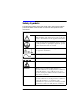
Safety Symbols The following symbols on the instrument and in the manual indicate precautions which must be taken to maintain safe operation of the instrument Safety Symbols The Instruction Documentation Symbol. The product is marked with this symbol when it is necessary for the user to refer to the instructions in the supplied documentation. Indicates the field wiring terminal that must be connected to earth ground before operating the equipment - protects against electrical shock in case of fault.
Safety Symbols The CE mark shows that the product complies with all relevant European Legal Directives. ISM 1-A This is a symbol of an Industrial, Scientific, and Medical Group 1 Class A product. The CSA mark is a registered trademark of the Canadian Standards Association, and indicates compliance to the standards defined by them. Indicates that a laser is fitted. The user must refer to the manual for specific Warning or Caution information to avoid personal injury or damage to the product.
About this Guide Overview This User’s Guide is a supplement to the manuals currently supplied with the HP/Agilent 8922 GSM Test Sets. The information contained in this User’s Guide is only relevant to the additional features of the HP/ Agilent 8922 GSM HSCSD Test System.
Contents 1. Understanding the HP/Agilent 8922 GSM HSCSD Test System Getting an overview of the HP/Agilent 8922 GSM HSCSD Test System .2 Features . . . . . . . . . . . . . . . . . . . . . . . . . . . . . . . . . . . . . . . . . . . . . . . . . . . .4 2. Setting up the HP/Agilent 8922 GSM HSCSD Test System Before you start . . . . . . . . . . . . . . . . . . . . . . . . . . . . . . . . . . . . . . . . . . . . . .6 Checking the HP/Agilent 8922 Requirements for HSCSD . . . . . . . . . . . .
Contents HSCSD screen . . . . . . . . . . . . . . . . . . . . . . . . . . . . . . . . . . . . . . . . . . . . . 1. Master downlink amplitude . . . . . . . . . . . . . . . . . . . . . . . . . . . . . . . 2. Slave offset . . . . . . . . . . . . . . . . . . . . . . . . . . . . . . . . . . . . . . . . . . . . 3. Master channel . . . . . . . . . . . . . . . . . . . . . . . . . . . . . . . . . . . . . . . . . 4. Master timeslot . . . . . . . . . . . . . . . . . . . . . . . . . . . . . . . . . . . . . . . . . 5.
Contents HSCSd:MASTer:DOWNlink:AMPLitude . . . . . . . . . . . . . . . . . . . . . . .50 HSCSd:MASTer:TCH:TLEVel . . . . . . . . . . . . . . . . . . . . . . . . . . . . . . . .51 HSCSd:MASTer:UPLink:AMPLitude . . . . . . . . . . . . . . . . . . . . . . . . . .52 HSCSd:MASTer:UPLink:AMPLitude:CONTrol . . . . . . . . . . . . . . . . . .53 HSCSD:MASTer:CALL:TYPE . . . . . . . . . . . . . . . . . . . . . . . . . . . . . . . .54 HSCSD:MASTer:CALL:RATE . . . . . . . . . . . . . . . . . . . . . . . . . . . . . .
Contents A. Upgrading the HOP Controller ROM and Firmware Upgrading the Hop Controller ROM . . . . . . . . . . . . . . . . . . . . . . . . . . . . 76 Upgrading the firmware . . . . . . . . . . . . . . . . . . . . . . . . . . . . . . . . . . . . .
1 Understanding the HP/Agilent 8922 GSM HSCSD Test System This chapter provides an overview of the HP/Agilent 8922 GSM HSCSD Test System.
Understanding the HP/Agilent 8922 GSM HSCSD Test System Getting an overview of the HP/Agilent 8922 GSM HSCSD Test System Getting an overview of the HP/Agilent 8922 GSM HSCSD Test System The HP/Agilent 8922 GSM HSCSD Test System option #K09, is ideal for mobile testing in research and development, and can also be used in manufacturing test applications. The HP/Agilent 8922 GSM HSCSD Test System option #K09 consists of two HP/Agilent 8922 P systems connected together in a master/slave setup as shown below.
Understanding the HP/Agilent 8922 GSM HSCSD Test System Getting an overview of the HP/Agilent 8922 GSM HSCSD Test System The HP/Agilent 8922 GSM HSCSD Test System is used either as a stand-alone instrument controlled manually via the front panel user interface, or as part of an automated test system controlled remotely over the GPIB bus using a PC or workstation. Note that manual and remote operation are not possible simultaneously.
Understanding the HP/Agilent 8922 GSM HSCSD Test System Features Features The HP/Agilent 8922 GSM HSCSD Test System supports the following features. The full range of features available in speech mode is maintained. • Support of fully variable power level of each active timeslot on the downlink. This provides complete freedom to control the amplitude of the downlinks. • Support of fully independent power control by protocol of each active timeslot on the uplink.
2 Setting up the HP/Agilent 8922 GSM HSCSD Test System This chapter describes how to connect and set up the HP/Agilent 8922 GSM HSCSD Test System.
Setting up the HP/Agilent 8922 GSM HSCSD Test System Before you start Before you start WARNING The HP/Agilent 8922 is a Safety Class 1 product (provided with a protective earth terminal). A safety earth ground must be provided from the mains power source to the product input wiring terminals, power cord, or supplied power cord set. Whenever it is likely that the protection has been impaired, the HP/Agilent 8922 GSM HSCSD Test System must be made inoperative and be secured against any unintended operation.
Setting up the HP/Agilent 8922 GSM HSCSD Test System Checking the HP/Agilent 8922 Requirements for HSCSD Checking the HP/Agilent 8922 Requirements for HSCSD To run the HSCSD functionality you need two HP/Agilent 8922 P systems (one acting as a master and one acting as a slave). Each system must be running firmware version C.01.06 or later and contain a HOP Controller ROM with a revision number of 19980730 or greater.
Setting up the HP/Agilent 8922 GSM HSCSD Test System Making the front panel connections Making the front panel connections Before you connect the two HP/Agilent 8922 P systems together to form the HP/Agilent 8922 GSM HSCSD Test System, ensure that both HP/ Agilent 8922 P systems are connected and calibrated as described in the HP/Agilent 8922 Multi-Band Test System Supplementary User’s Guide.
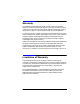
Setting up the HP/Agilent 8922 GSM HSCSD Test System Making the rear panel connections Making the rear panel connections Before connecting the two HP/Agilent 8922 P systems to form the HP/ Agilent 8922 GSM HSCSD Test System, ensure that both HP/Agilent 8922 P systems are connected and calibrated as described in the HP/ Agilent 8922 Multi-Band Test System Supplementary User’s Guide.
Setting up the HP/Agilent 8922 GSM HSCSD Test System Making the rear panel connections Figure 2-2 Rear panel connections GPIB cable System bus cable 10 MHz reference cable Master 10 Slave Chapter 2
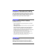
Setting up the HP/Agilent 8922 GSM HSCSD Test System Enabling the HSCSD functionality Enabling the HSCSD functionality You must enable the HSCSD test functionality within the HP/Agilent 8922 using the keycard supplied as follows. Step 1. Power on the HP/Agilent 8922. Step 2. Insert the keycard into the HP/Agilent 8922. Figure 2-3 Inserting the keycard into the HP/Agilent 8922 Step 3. Press the TESTS key on the front panel of the HP/Agilent 8922 to access the TESTS screen.
Setting up the HP/Agilent 8922 GSM HSCSD Test System Enabling the HSCSD functionality Figure 2-4 Tests screen Step 4. Set Location to CARD. Step 5. Select the Procedure field and select ENABLE as the procedure. Step 6. Select the Run Test field or press the L1 key on the front panel of the HP/Agilent 8922 to run the program. The option HSCSD Master is now present in the Instrument Type field in the CONFIGURE screen indicating that the HSCSD functionality is correctly enabled.
Setting up the HP/Agilent 8922 GSM HSCSD Test System Enabling the HSCSD functionality Figure 2-5 Config screen HSCSD MASTER C.01.06 To disable HSCSD To disable the HSCSD functionality, repeat steps 1 to 4 of the procedure functionality for enabling the functionality, set the Procedure field to DISABLE in step 5 and complete the rest of the procedure.
Setting up the HP/Agilent 8922 GSM HSCSD Test System Calibrating the overall system Calibrating the overall system There is an RF loss through the system from the slave unit's reported output level to that observed by the mobile due to cable loss and a nominal 7 dB loss through the system.
3 Manual operation This chapter describes the basic procedures required to manually operate the HP/Agilent 8922 GSM HSCSD Test System. For more details on operating procedures, refer to the HP/Agilent 8922M⁄S User’s Guide.
Manual operation Configuring the system Configuring the system To configure the HP/Agilent 8922 GSM HSCSD Test System for manual operation, proceed as follows. NOTE You must configure the slave unit first as a frame reset is sent from the master unit to the slave unit as soon as the master unit is activated. The slave unit must be ready to receive this frame reset.
Manual operation Configuring the system The slave unit’s GPIB address is now automatically set to 15 (seen in the IO Config screen) which is the default Slave Address setting on the master unit. The slave unit’s GPIB address must be the same as the Slave Address setting on the master unit and this helps to ensure this. The slave unit’s Operating Mode is also automatically set to Test Mode (seen in the Cell Status screen).
Manual operation Establishing a call Establishing a call You establish a call in the same way as for a speech call. Step 1. Ensure that the master timeslot is the timeslot currently being measured on the master unit. To do this, navigate to the HSCSD control screen on the master unit and set the Measure field to Master. If you do not do this the HP/Agilent 8922 does not see the signalling from the mobile, and call set up fails. Step 2.
Manual operation Making measurements Making measurements Once a call is established, you can make measurements as before—see the HP/Agilent 8922 User’s Guide for more details. Note however that there are two new factors which you need to consider: choosing which timeslot to perform measurements on, and performing BER on the twounit system. Choosing which timeslot to measure Any HSCSD instrument can measure the master or the slave timeslot.
Manual operation Changing power levels, timeslot and channels Changing power levels, timeslot and channels You can change downlink and uplink power, TCH timeslot, and TCH ARFCN simply be typing in a new value on the HSCSD control screen. A dual band channel assignment can be performed using the existing procedure.
Manual operation Ending a call Ending a call Ending a call is the same procedure as that used for a standard HP/ Agilent 8922 Test System, however the master unit must be measuring the master timeslot. Refer to the HP/Agilent 8922M⁄S User’s Guide for more information. NOTE To ensure that the call ends cleanly, the master unit must be measuring the master timeslot when the call is ended.
Manual operation Ending a call 22 Chapter 3
4 Screens This chapter describes the screens that are part of the HP/Agilent 8922 GSM HSCSD Test System. For more details on all other screens, refer to the HP/Agilent 8922M⁄S User’s Guide. These screens are only available for firmware revision C.01.06 and later.
Screens Config screen Config screen Figure 4-1 Config screen 1 2 C.01.06 1. Instrument type Type menu Choices Speech HSCSD Master HSCSD Slave Default Speech HSCSD Master and HSCSD Slave indicate that the HP/Agilent 8922 is part of a multi-box solution. Note that selecting HSCSD Master temporarily sets the GPIB control field on the IO Config screen to Control (this happens whenever the master unit sends a user change to the slave unit).
Screens Config screen • set the slave GPIB address to match the address of the slave unit • make sure that the addresses of the slave and master units are different • make sure that no other GPIB controller is active and attached to the system NOTE If you are operating the HP/Agilent 8922 GSM HSCSD Test System manually do not connect another GPIB controller such as a PC to the GPIB bus.
Screens Config screen 2. Slave address Type integer Units none (HP-IB address) Limits 0 thru 30 Default 15 The Slave address field appears only if you have selected HSCSD Master as the instrument type and is the address used by the master unit to send GPIB commands to the slave unit. This is only used when the instrument is being operated manually. NOTE You must ensure that the GPIB address on the slave unit matches the value configured in the Slave address field on the master unit.
Screens HSCSD screen HSCSD screen Figure 4-2 HSCSD Control screen 1 15 2 3 4 5 6 7 8 9, 12 16 17 10, 13 12 14 1. Master downlink amplitude Type floating point Units dBm only Limits (GSM900) -127.0 thru +1.0 Limits (E-GSM) -127.0 thru +1.0 Limits (DCS1800) -127.0 thru -12.0 Limits (PCS1900) -127.0 thru -12.0 Default -85.0 The Master downlink amplitude field shows the downlink amplitude of the master TCH.
Screens HSCSD screen adding an offset (see page 28) to this value. NOTE The default is reset when you select the instrument type (see page 24). 2. Slave offset Type floating point Units dBm only Limits (GSM900) -100.0 thru +100.0 Default 0.0 The Slave offset field determines the downlink amplitude of the master TCH by selecting the difference in amplitude between the master and slave amplitudes. Below this field there is a read-only reminder of the absolute level of the slave TCH.
Screens HSCSD screen Limits (GSM900) 1 thru 124 Limits (E-GSM) 0 thru 124; 995 thru 1024 Limits (DCS1800) 512 thru 885 Limits (PCS1900) 512 thru 810 Default (GSM900) 30 Default (E-GSM) 30 Default (DCS1800) 512 Default (PCS1900) 512 The Master Channel field shows the ARFCN of the TCH. There is only one ARFCN, as HSCSD systems place all timeslots on the same ARFCN. On a slave unit, setting this field changes the ARFCN of the downlink TCH and analyzer appropriately.
Screens HSCSD screen 4. Master timeslot Type integer Units none (timeslot) Limits 2 thru 5 Default 4 The Master timeslot field indicates which timeslot is used for the master TCH. As the slave TCH is always in the timeslot immediately after the master, changing this field sets the slave timeslot to the value “master timeslot plus one”. On a master unit or a single unit, the value of this field is always the same as the TCH timeslot field on the Cell Status screen.
Screens HSCSD screen 6. Call Type Type Toggle Units None Default 2x2 Values 2x2 or 2x1 The Call Type field determines which type of HSCSD call the HP/ Agilent 8922 establishes the next time a call is initiated. If you select 2x1, the HP/Agilent 8922 tries to establish a call with 2 downlinks and 1 uplink when a call is next initiated.
Screens HSCSD screen 7. Data rate Type Toggle Units None Choices “9.6” or “14.4” Default “9.6” The Data rate field determines the data rate associated with the HSCSD 2x2 call. Selecting '9.6' sets up a call at 9.6 kbit/s per timeslot (19.2 kbit/s) and selecting '14.4' sets up a call at 14.4 kbit/s per timeslot (28.8 kbit/s). NOTE The value of the Data rate field can not be changed while a call is in progress. 8.
Screens HSCSD screen 9. Master Tx level Type integer Units none (Tx level) Limits (GSM900) 1 thru 19 Limits (E-GSM) 1 thru 19 Limits (DCS1800) 0 thru 15 Limits (PCS1900) 0 thru 15; 30 thru 31 Default (GSM900) 15 Default (E-GSM) 15 Default (DCS1800) 10 Default (PCS1900) 10 On a master unit, the Master Tx level field requests a new transmit level for the uplink master TCH. On a slave unit, this field does not make this request.
Screens HSCSD screen 10. Master input level Type float Units dBm only Limits (GSM900) -27 thru +41.0 Limits (E-GSM) -27 thru +41.0 Limits (DCS1800) -47 thru +33.0 Limits (PCS1900) -47 thru +33.0 Default (compatibility mode) 33.0 Default (GSM900) 13.0 Default (E-GSM) 13.0 Default (DCS1800) 10.0 Default (PCS1900) 10 The Master Input level field sets the expected power of the master uplink TCH.
Screens HSCSD screen 11. Master mode Type menu Choices “Manual”, “MS Tx Lev” Default (compatibility mode) “Manual” Default (standard mode) “MS Tx Lev” The Master mode field either makes or breaks the link between the Master Tx level (see page 33) and the Master input level (see page 34). NOTE Note that in standard mode, setting either of these other values change the Master mode field. See the description of these fields for an explanation of the level control mode. 12.
Screens HSCSD screen On both units, if the instrument is operating in standard mode, setting this field changes the slave control field (see page 37) to MS Tx Lev, then calculates and sets the slave expected input level (see page 36). If the instrument is operating in compatibility mode, setting this field only changes the slave expected input level when the slave control type is MS Tx Lev. NOTE The default is reset when you select the instrument type (see page 24). 13.
Screens HSCSD screen control type is MS Tx Lev, then the instrument returns an error (Can’t change setting while MS TX Lev mode is selected.) and does not make the setting. NOTE The default is reset when you select the instrument type (see page 24). 14.
Screens HSCSD screen 15. Mobile reports The Mobile Reports are the same uplink SACCH reports as appear on the Cell Status screen. The reports are taken from whichever uplink timeslot is currently being analysed. You make this choice using the Measurement timeslot field (see page 32). 16. Peak power display The Peak Power display is the same measurement as appears on the Cell Status screen. The measurement is made on whichever uplink timeslot is currently being analyzed.
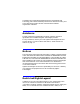
Screens Fast BER Screen Fast BER Screen One extra field, labelled Loopback, appears in the Fast Bit Error screen, when the HP/Agilent 8922 is in 2x1 mode. Figure 4-3 Fast BER screen The Loopback field is a toggle field and allows the choice of either master or slave. This instructs the mobile to either loopback the master channel on the downlink to the master uplink or loopback the slave downlink to the master uplink.
Screens Fast BER Screen Loopback Type toggle Choices “Master”, “Slave” Default “Master” The Loopback field selects which downlink slot is looped back on the master uplink.
5 Remote operation This chapter explains how to operate the HP/Agilent 8922 GSM HSCSD Test System over the GPIB. The new GPIB commands for the HP/Agilent 8922 GSM HSCSD Test System are detailed. For the syntax format of all other GPIB commands, see the Agilent 8922M⁄S Programming Reference Guide.
Remote operation Introduction Introduction The general principle of operation is that the settings on the slave unit are relative to the settings on the master unit which allows the manual and remote interfaces to operate in the same way. It is therefore necessary to always consider the relationship between the two timeslots. Call setup and changing channels are handled by the master unit. However, it is vital that the slave unit remains on the same channel and timeslot (offset by one) as the master unit.
Remote operation Configure Subsystem GPIB Commands Configure Subsystem GPIB Commands Figure 5-1 Configure Instrument Type comand syntax INSTrument[:TYPE]? CONFigure INSTrument[:TYPE] Sp string CONFigure:INSTrument[:TYPE] Description Sets what role the HP/Agilent 8922 plays in the multi-slot test system. This selection differs from manually selecting the instrument type in two ways: the GPIB status does not change to Control, and the unit’s GPIB address does not change.
Remote operation Display Subsystem GPIB Commands Display Subsystem GPIB Commands Figure 5-2 Display Screen command syntax SCReen DISPlay Sp string DISPlay:SCReen HSCSD Description This command selects the HSCSD control screen (or an error screen if the system is not upgraded to run HSCSD).
Remote operation HSCSD Subsystem GPIB Commands HSCSD Subsystem GPIB Commands Chapter 5 45
Remote operation HSCSD Subsystem GPIB Commands Figure 5-3 HSCSd HSCSD command syntax (master unit) MASTer TCH ARFCn? ARFCn Sp integer Sp integer Sp integer TSLot? TSLot TLEVel? TLEVel STATus TCH ARFCn? TSLot? DOWNlink AMPLitude? AMPLitude UPlink real units AMPLitude? AMPLitude real CONTRol? CONTRol CALL Sp string TYPE? TYPE Sp string RATE Sp string TSLot Sp string RATE? MEASure 46 Chapter 5
Remote operation HSCSD Subsystem GPIB Commands Figure 5-4 HSCSD command syntax (slave unit) HSCSd SLAVe TCH TLEVel? TLEVel STATus Sp integer SYNC? TCH DOWNlink TSLot? AMPLitude? AMPLitude real OFFSet real OFFSet? UPlink AMPLitude? AMPLitude real CONTrol? CONTrol Chapter 5 Sp string 47
Remote operation HSCSD Subsystem GPIB Commands HSCSd:MASTer:TCH:ARFCn Description Setting this during a call forces a channel assignment to the given channel. Note that existing channel assignment commands sent to a master or single unit have the same effect. In particular, a dual band assignment must be performed using the existing dual band commands.
Remote operation HSCSD Subsystem GPIB Commands HSCSd:MASTer:STATus:TCH:TSLot Description Setting this during a call changes the master timeslot. Note that existing timeslot commands sent to a master or single unit have the same effect. When the system is idle (that is, not on a call) this sets the timeslot which will be used when the next command is established. In a multi-box system, this command must also be sent to the slave unit. Note that the slave timeslot is always the slot following the master.
Remote operation HSCSD Subsystem GPIB Commands HSCSd:MASTer:DOWNlink:AMPLitude Description This sets the downlink amplitude of the master TCH. In all cases, this sets the TCH level. To change the amplitude of the GSM BCH in a dual band system, use the existing command DUALband:ATTenuation:GBCh. See the HP/Agilent 8922 Multi-Band Test System Supplementary User’s Guide for more details. This command must also be sent to the slave unit.
Remote operation HSCSD Subsystem GPIB Commands HSCSd:MASTer:TCH:TLEVel Description During a call, this sets the Tx level of the master TCH. When the system is idle (that is, not on a call), this sets the Tx level to be used when the next call is established. Note that this value is used initially for both timeslots. It is only once the TCH is established, and the mobile begins to decode the downlink SACCH, that the individual Tx levels are used.
Remote operation HSCSD Subsystem GPIB Commands HSCSd:MASTer:UPLink:AMPLitude Description This sets the expected input level of the master TCH. In standard mode, this sets the master’s uplink amplitude control to MANUAL. In compatibility mode, if the master’s uplink amplitude control is set to MS TX LEV then an error message Can’t change setting while MS TX Lev mode is selected. occurs and the setting is not performed.
Remote operation HSCSD Subsystem GPIB Commands HSCSd:MASTer:UPLink:AMPLitude:CONTrol Description This defines the relationship between the master’s Tx level, and the master’s expected uplink amplitude. MS TX LEV indicates that setting the master’s Tx level also sets the master’s expected uplink amplitude. MANUAL indicates that setting the master’s expected uplink amplitude is independent from the value of the master’s Tx level.
Remote operation HSCSD Subsystem GPIB Commands HSCSD:MASTer:CALL:TYPE Description This command selects which type of call the HP/Agilent 8922 will set up the next time a call is initiated.
Remote operation HSCSD Subsystem GPIB Commands HSCSD:MASTer:CALL:RATE Description This command selects the data rate of the call that the HP/Agilent 8922 will set up the next time a call is initiated. Syntax HSCSD:MASTer:CALL:RATE HSCSD:MASTer:CALL:RATE? Command options Type toggle Units none Choices 9.6 or 14.4 Default 9.
Remote operation HSCSD Subsystem GPIB Commands HSCSd:SLAVe:STATus:SYNC Description This read-only field indicates whether or not the slave unit is synchronised with the master unit. The status is set to DISABLED when you set the instrument type to HSCSD SLAVE. This must be done before configuring the master unit. When the master unit is configured as HSCSD MASTER, a frame reset is sent from the master unit to the slave unit.
Remote operation HSCSD Subsystem GPIB Commands HSCSd:SLAVe:STATus:TCH:TSLot? Description This query returns the absolute timeslot. For example, if the master’s timeslot is 3, because the slave’s timeslot offset is fixed at +1, HSCSd:SLAVe:STATus:TCH:TSLot? would return 4. Syntax HSCSd:SLAVe:STATus:TCH:TSLot? Command options Not applicable.
Remote operation HSCSD Subsystem GPIB Commands HSCSd:SLAVe:DOWNlink:AMPLitude:OFFSet Description This sets the amplitude offset (in dBs) of the slave timeslot, using the master’s downlink amplitude as a reference. The resulting amplitude must lie within the normal downlink power range. If not, the error Disallowed due to pulse mod configuration is produced, and the setting is ignored.
Remote operation HSCSD Subsystem GPIB Commands HSCSd:SLAVe:TCH:TLEVel Description During a call, this sets the Tx level of the slave TCH. When the system is idle (that is, not on a call), this sets the Tx level to be used when the next call is connected and the slave TCH is established. Note that this is not the Tx Level first used to establish the TCH. In standard mode, this also sets the slave’s uplink amplitude control to MS TX LEV, and calculates and sets the slave’s expected uplink amplitude.
Remote operation HSCSD Subsystem GPIB Commands HSCSd:SLAVe:UPLink:AMPLitude Description This sets the expected input level of the slave timeslot. In standard mode, this sets the slave’s uplink amplitude control to MANUAL. In compatibility mode, if the slave’s uplink amplitude control is set to MS TX LEV then an error occurs and the setting is not performed. If the measurement timeslot (see page 43) is set to Slave, the analyser level of the unit is set to this value.
Remote operation HSCSD Subsystem GPIB Commands HSCSd:SLAVe:UPLink:AMPLitude:CONTrol Description This defines the relationship between the slave Tx level, and the slave expected uplink amplitude. MS TX LEV indicates that setting the slave’s Tx level also sets the slave’s expected uplink amplitude. MANUAL indicates that setting the slave’s expected uplink amplitude is independent from the value of the slave’s Tx level.
Remote operation Remote operating procedures Remote operating procedures NOTE For remote operation to work: • the two HP 8922P units must be put into master and slave mode by remote control • HSCSD settings must be made on both HP/Agilent 8922 P units Configuring the system The slave unit must be configured and initialized before the master unit. Note that unlike manual configuration, the GPIB address of the slave unit does not have to be synchronized on both units.
Remote operation Remote operating procedures Establishing a call The procedure for establishing a call is the same as for speech. Note however, that you must be measuring the master uplink in the master unit.
Remote operation Remote operating procedures Changing channels, timeslot and power levels Performing a channel assignment is a single instruction. Note that the slave unit must be kept in step with the master and the master must be measuring the master uplink prior to performing a channel assignment. Note also that a dual band channel assignment can be performed using the existing procedures.
Remote operation Remote operating procedures Ending a call Ending a call is performed in the same way as for speech. NOTE The master or single unit must be measuring the master timeslot for the call to end cleanly. OUTPUT Master;”CELL:CALL:END” Note that only the master unit is used.
Remote operation Example code showing a dual-band handover from E-GSM to DCS Example code showing a dual-band handover from E-GSM to DCS Some example code is listed below which performs a dual-band handover from E-GSM to DCS on an HP/Agilent 8922 GSM HSCSD Test System. The technique is to use the standard dual-band command sequence, but send this to both HP/Agilent 8922 units.
Remote operation Example code showing a dual-band handover from E-GSM to DCS 350 360 370 380 390 400 410 420 430 440 450 460 470 480 490 500 510 520 530 540 550 560 570 580 590 600 610 620 630 640 650 660 670 680 690 700 720 730 740 750 760 770 780 790 800 810 ! enabled, it will IMMEDIATELY return ENABLED ! ! Select the HSCSD screen - it's easier to see what's ! happening for now OUTPUT Master;"DISP HSCSD" OUTPUT Slave;"DISP HSCSD" ! ! Dial in RF losses ! OUTPUT Master;"Conf:OFLevel:RFInOut ";-1*Master_los
Remote operation Example code showing a dual-band handover from E-GSM to DCS 820 830 840 850 860 870 880 890 900 910 920 930 940 950 960 68 ! OUTPUT Master;"DualBand:TCHC:Exec" OUTPUT Slave;"DualBand:TCHC:Exec" WAIT 3 ! OUTPUT Master;"Disp HSCSD" OUTPUT Slave;"Disp HSCSD" ! ! ! Terminate program ! LOCAL Master LOCAL Slave STOP END Chapter 5
6 Returning equipment for repair 69
Returning equipment for repair Return Procedure Return Procedure If you need to return your HP/Agilent 8922 or HP/Agilent 83220 to Agilent Technologies, first obtain the correct Service Center shipping address from your local sales office and proceed as follows. Refer to Sales and Service Offices on page 72 for contact information. CAUTION Instrument damage can result from using packaging materials other than the original shipping materials or equivalent. Never use styrene pellets as packaging materials.
Returning equipment for repair Return Procedure enough to accommodate the instrument. Allow at least 7 to 10 cms on all sides of the instrument for packing material. 3. Surround the instrument with 7 to 10 cms of packing material to protect it and prevent it from moving in the carton. 4. Seal the carton with strong nylon adhesive tape. 5. Mark the carton "FRAGILE, HANDLE WITH CARE." 6. Retain copies of all shipping papers.
Returning equipment for repair Sales and Service Offices Sales and Service Offices Any adjustment, maintenance, or repair of this product must be performed by qualified personnel. Contact your customer engineer through your local Agilent Technologies Service Center. You can find a list of local service service representatives on the web at. http://www.agilent-tech.com/services/English/index.html You can also contact one of the following centers and ask for a test and measurement sales representative.
Returning equipment for repair Sales and Service Offices Canada: Agilent Technologies Canada Inc. 5150 Spectrum Way, Mississauga, Ontario L4W 5G1 (tel) 1 877 894 4414 Europe: Agilent Technologies Test & Measurement European Marketing Organisation P.O. Box 999 1180 AZ Amstelveen The Netherlands (tel) (31 20) 547 9999 Latin America: Agilent Technologies Latin American Region Headquarters 5200 Blue Lagoon Drive, Suite #950 Miami, Florida 33126 U.S.A.
Returning equipment for repair Sales and Service Offices 74 Chapter 6
A Upgrading the HOP Controller ROM and Firmware This chapter describes how to upgrade the HOP Controller ROM and firmware on the HP/Agilent 8922 P to allow it to run the HSCSD functionality.
Upgrading the HOP Controller ROM and Firmware Upgrading the Hop Controller ROM Upgrading the Hop Controller ROM CAUTION Perform the following procedures at a static safe workstation. The printed circuit assemblies in the instrument are very sensitive to static electricity. WARNING Before disassembling the instrument, turn the line switch OFF and unplug the instrument. Failure to unplug the instrument may result in personal injury.
Upgrading the HOP Controller ROM and Firmware Upgrading the Hop Controller ROM Figure A-1 Removing the top cover 1 3 4 2 (Both Sides) (Both Sides) SIDE VIEW Step 3. Remove RF covers A and B using a TX-15 screw driver (see below). Figure A-2 Removing the RF covers A and B Cover A Cover B Step 4. Disconnect any necessary cables to free the A33 HOP Controller board. Step 5. Remove the A33 HOP Controller board.
Upgrading the HOP Controller ROM and Firmware Upgrading the Hop Controller ROM Figure A-3 Removing the A33 Hop Controller Board Step 6. Remove the A33 U62 HOP Controller ROM. You may need to force when removing and replacing the ROM. Figure A-4 Removing the A33 U62 HOP Controller ROM U62 Step 7. Insert the new A33 U62 HOP Controller ROM making sure that the orientation of the ROM matches the template shown on the board.
Upgrading the HOP Controller ROM and Firmware Upgrading the Hop Controller ROM Step 8. Reinstall the A33 HOP Controller board. Step 9. Reconnect the cables. Step 10. Replace the instrument top cover.
Upgrading the HOP Controller ROM and Firmware Upgrading the firmware Upgrading the firmware The HP/Agilent 8922 GSM HSCSD Test System host firmware is downloaded to the instrument over the GPIB interface. This is performed using an external controller with an GPIB interface and the HP BASIC programing language. Contact your local Agilent TechnologiesCustomer Service Center or Representative for more information.