
Specifications


12
Measurement applications
Solid black series name indicates the feature is available on
that series, while gray series name with strikethrough indi-
cates the feature is not available on that series. For example;
PNA: Available on PNA Series
PNA: Not available on PNA Series
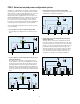
□ Time domain (Option 010)
PNA-X PNA PNA-L
This option enables the analyzer to view reflection and trans-
mission responses in time or distance. Use time domain to tune
filters, gate out the response of fixtures and cables, characterize
the impedance of transmission lines and more. If eye-diagram anal-
ysis, W-element modeling or high-speed interconnect testing is
required, PLTS N1930B software must be used.
□ Frequency offset (Option 080)
PNA-X PNA PNA-L
This option enables the analyzer to set the source frequency
independently from where the receivers are tuned, and is
required to configure an external source using External Device
Configuration. This ability is important for measuring amplifiers,
mixers, and frequency converters.
□ Scalar-calibrated converter measurements (Option 082)
PNA-X PNA PNA-L
With a simple setup and calibration, this application delivers the
highest accuracy for scalar conversion-loss/gain measurements
by combining one-port and power-meter calibrations to remove
mismatch errors. Option 082 provides an intuitive and easy-to-use
user interface for setting up mixer and converter measurements,
with single or dual conversion stages. It can control the analyz-
er’s built-in source(s) as well as external signal generators for
use as LO signals. Supported external sources include the Agilent
ESG, PSG, and MXG Series, as well as other SCPI-controlled
signal generators. Option 082 requires Option 080, and cannot be
ordered with Option 083. It is compatible with Option 084, which
enables measurements of converters with internal LOs.
□ Vector- and scalar-calibrated converter measurements (Option 083)
PNA-X PNA PNA-L
This application includes the scalar mixer/converter plus
phase (SMC+Phase) measurement class that provides fully
calibrated conversion gain/loss, relative phase, and absolute
group delay measurements of mixers and converters without
the need for reference or calibration mixers. Eliminating the
calibration mixer requires a U9391C/F/G comb generator and
an external DC power supply capable of sourcing +15 V to 300 mA
for U9391C/F or 800 mA for U9391G
1
. A vector mixer/converter
measurement (VMC) class is also included for measurements
with the least amount of trace noise for phase/delay measure-
ments. Option 083 provides an intuitive and easy-to-use user
interface for setting up mixer and converter measurements,
with single or dual conversion stages. It can control the
analyzer’s built-in source(s) as well as external signal genera-
tors for use as LO signals. Supported external sources include
the Agilent ESG, PSG, and MXG Series, as well as other SCPI-
controlled signal generators. Option 083 requires Option 080,
and cannot be ordered with Option 082. It is compatible with
Option 084, which enables measurements of converters with
internal LOs.
□ Embedded LO measurements (Option 084)
PNA-X PNA PNA-L
This option tunes the analyzer’s receivers to the output frequency
of the converter under test without the need for access to internal
LOs or a common reference signal. For converters with embedded
LOs, this option requires Option 082 (enables match-corrected
conversion loss/gain measurements) or Option 083 (enable abso-
lute group delay measurements). This option also works with
Option 086 gain compression application, Option 087 intermodula-
tion distortion application, and Option 028/029/H29 noise figure
applications.
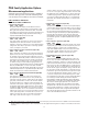
□ Gain compression application (Option 086)
PNA-X PNA PNA-L
The gain compression application (GCA) provides input power,
output power, gain, and phase at the compression point of an
amplifier or frequency converter, over a specified frequency
range. GCA's SMART Sweep is very fast and easy-to-use. GCA
also includes a guided calibration that corrects for absolute
power levels, frequency response, and mismatch errors.
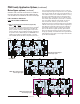
□ Intermodulation distortion application (Option 087)
PNA-X PNA PNA-L
The intermodulation distortion (IMD) application makes it very
easy to set up and calibrate swept-IMD measurements of both
amplifiers and frequency converters. It controls the frequency and
power of internal and external sources and tunes the receivers to
the main tones as well as the IMD products in a single measure-
ment channel. The user can sweep either the center frequency of
the two stimulus signals, the frequency spacing of the two stimu-
lus signals about a fixed center frequency, or the power of one or
both stimulus signals or the power of the LO signal. The analyzer
can measure intermodulation distortion products of order 2, 3, 5,
7, or 9, and can display the associated intercept points. In addi-
tion, an IM Spectrum mode gives a spectrum-analyzer-like display
for confirming or trouble-shooting measurements. Requires
Option 080. Not available with PNA Option 200 and 400. When
configured with a 2-port PNA or 2-port PNA-X with either Option
200 or 219, an external signal generator and a combiner are
required. When configured with a 4-port PNA or 4-port PNA-X
with Option 400 or 419, the two internal sources and an unused
test port coupler configured as a combiner can be used for two-
tone IMD measurements. When configured with PNA-X Option
224 or 423, the two internal sources and internal combiner can be
used for two-tone IMD measurements.
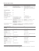
PNA Family Application Options
1. When using a comb generator as a phase reference for calibration, the start frequency of the measurement must be ≥ 55 MHz. For measurements between
50 GHz and 67 GHz, an additional high-pass filter is required (two back-to-back Agilent V281A waveguide-to-coax adapters recommended; must be ordered
separately).