HORUS DIGITAL NIGHT VISION SCOPE USER MANUAL
© 2022 AGM Global Vision, LLC. All rights reserved. This documentation is subject to change without notice. No parts of this manual, in whole or in part, may be copied, photocopied, translated, or transmitted by any electronic medium or in machine-readable form without the prior written permission of AGM Global Vision, LLC. If you have questions that are not covered in this manual, or need service, contact AGM Global Vision customer support for additional information prior to returning a product.
FCC INFORMATION Please take attention that changes or modification not expressly approved by the party responsible for compliance could void the user’s authority to operate the equipment. This equipment complies with FCC/IC RSS-102 radiation exposure limits set forth for an uncontrolled environment. FCC compliance: This product has been tested and found to comply with the limits for a Class B digital device, pursuant to Part 15 of the FCC Rules.
EU CONFORMITY STATEMENT This product and - if applicable - the supplied accessories too are marked with “CE” and comply therefore with the applicable harmonized European standards listed under the EMC Directive 2014/30/EU, RE Directive 2014/53/EU, the RoHS Directive 2011/65/EU 2012/19/EU (WEEE directive): Products marked with this symbol cannot be disposed of as unsorted municipal waste in the European Union.
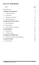
LIST OF CONTENTS TITLE PAGE Safety Summary 6 1. GENERAL INFORMATION 8 1.1 System Description 8 1.2 Key Features 9 1.3 Standard Components 1.4 Optional Equipment 2. OPERATING INSTRUCTIONS 10 11 12 2.1 Basic Operations 12 2.2 Main Function 21 2.3 Client Software Introduction 35 3. MAINTENANCE 36 3.1 Maintenance 36 3.2 Troubleshooting 37 4. WARRANTY INFORMATION 4.1 Warranty Information and Registration 39 39 5. SPECIFICATIONS 42 5.
SAFETY SUMMARY • • • Read and follow all instructions Read all warnings Only use the attachments/accessories manufacturer • All service must be provided by the manufacturer specified by the WARNING: This product contains natural rubber latex, which may cause potentially fatal allergic reactions! If you are allergic to latex, it is important that you strictly avoid exposure to products that contain it.
• • • • • • • The external removable battery type is CR123A, and the max. rated voltage and capacity are 3 VDC/2 A and 1600 mA. Dispose of used batteries in conformance with the instructions provided by the battery manufacturer. Make sure the battery temperature is between 0°C to 45°C (32°F to 113°F) when charging. Install the external battery before the built-in battery runs out, or the device cannot be turned on. Confirm there is no flammable material within 2 m of the charger during charging.
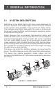
1 GENERAL INFORMATION 1.1 SYSTEM DESCRIPTION AGM Horus is the digital day & night vision scope developed for 24 hours operation in all ambient light. The Horus can be mounted to the weapon using standard scope mounts for 30mm tubes. The traditional-style 30mm tube meets the needs of professional hunters who value traditions and technological superiority, ensure an extreme shooting range.
TABLE 1-1. MAIN PARTS ITEM DESCRIPTION 1 Lens Cap 2 Focus Ring 3 USB Interface Cover 4 Battery Cover 5 Operation Wheel 6 Power Button 7 Palette Switch Button 8 Capture Button 9 Eyepiece Focus Ring 10 Eyepiece 1.2 KEY FEATURES • 1440x1080 High-definition sensor • Supports Day/Night mode • Supports audio recording • Supports recoil-activation recording • Supports video recording and snapshot, • Built-in EMMC (64 GB) • 1024*768 resolution 0.
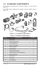
1.3 STANDARD COMPONENTS The standard components are shown in Figure 1-2 and listed in Table 1-2. The ITEM column indicates the number used to identify items in Figure 1-2. 2 1 3 9 6 8 7 5 4 11 10 12 FIGURE 1-2. STANDARD COMPONENTS TABLE 1-2.
1.4 OPTIONAL EQUIPMENT Optional items are shown in Figure 1-3 and listed in Table 1-3. 3 1 2 FIGURE 1-3. OPTIONAL EQUIPMENT TABLE 1-3. OPTIONAL EQUIPMENT ITEM DESCRIPTION PART NO. 1 AGM-2116 ADM Quick Release Mount for Horus TS35/50. Quick release mount with two 30mm rings. 1.47” (37.3 mm) centerline height.
2 OPERATING INSTRUCTIONS 2.1. BASIC OPERATIONS 2.1.1 UNPACKING The following steps must be completed prior to each mission. 1. Open the carrying case, remove the device, and verify that all components are included. 2. Inspect the device for any obvious evidence of damage to the optical surfaces, body, eyecup, operation buttons, etc. Ensure that all optical surfaces are clean and ready for use. Clean all optical surfaces with a lens tissue. 2.1.
1. Unscrew the USB interface cover (Figure 2-1, A). 2. Connect the power adapter to the scope’s interface port (B) using the USB cable (C). in the 3. Plug in the power adapter and charge the device. Icon FOV of scope indicates the charging process. The color LED (D) near USB port indicates the charging status. TABLE 2-1. BATTERY LED INDICATOR STATUS INDICATOR FUNCTIONS Flashing Red & Green Error occurred. Solid Red Battery is properly charging. Solid Green Battery is fully charged.
2.1.4 CONTROL BUTTONS The Horus controls are shown in Figures 2-3 and are defined in Tables 2-2. Each button is responsible for some functions selected by short press or long press (hold) the button. Pushing a button for 2+ second is considered “long press” (hold). 3 4 5 1 2 FIGURE 2-3. HORUS CONTROLS TABLE 2-2.
2.1.6 AUTO POWER OFF In the “Auto Power Off” menu you can set the time for the automatic shutdown of the device. 1. Hold the wheel to go to the menu. , and press the wheel to select the 2. Rotate the wheel to select auto power off time as required ( OFF / 30 min / 45 min ). 3. Hold the wheel to save and exit. 2.1.7 STANDBY MODE Standby mode is used to save battery power.
NOTE: You must perform the focus adjustment before any further use of the riflescope. 2.1.9 DIGITAL ZOOM In the live view mode, rotate the operation wheel to switch the digital zoom of the device between 1×, 2×, and 4×. The image magnification value is displayed on the screen: 3.5x, 7x, 14x 2.1.10 RETICLE TYPE SWITCHING 5 types of reticles can be selected. To quickly switch between (see section different reticles types, press the WHEEL button 2.2.7 for more detail). 2.1.
NOTE: When captured, the image freezes for 1 second and a prompt shows on the display. For exporting captured videos and pictures, refer to Files Export. 2.1.12 FILE EXPORT 1. Unscrew the USB interface cover. Connect the thermal scope to your PC with USB cable and open the detected disk. 2. Open computer disk and select the disk of device. Go to the DCIM folder and find the folder named after the capture year and month.
A B D C FIGURE 2-6. INSTALLATION WITH SCOPE RINGS 1. Remove every screw (A) along with the upper parts (B) of the scope rings. 2. Loosen the fixing screws (C) of the lower parts (D) of the rings and install them on the rail. 3. Then, you can try to fit the scope before placing the upper rings. The scope rings need to be at a proper distance from the objective bell as well as the turrets so that the eye relief adjustment can be done. 4.
H G F PUSH A D UNLOCK C B UNLOCKED CLAMPING DEVICE (UNDERSIDE VIEW) TURN E FIGURE 2-7. INSTALLATION WITH QUICK RELEASE MOUNT 3. Affix the mount to the rail by locking the levers (B). 4. Verify that the clamping devices are firmly holding the mount. If necessary, adjust each clamping device’s lever-cam lock as detailed below: 1) Remove the QR mount from the rail. 2) With the clamping device unlocked, push the cam (D) towards the arrow, which will cause the nut (E) to slide out of its hole.
7. Place the QR mount with the scope mounted on the weapon rail and affix it by locking the levers. Adjust the eye relief. Position the scope far enough to keep your eye safe from recoil. 8. Turn on the power of the scope and activate the reticle. 9. With the rifle held level, rotate the scope until the reticle is precisely vertical and horizontal. 10. Check the position of the scope and tighten the ring screws. Ensure an even fit by alternately tightening the screws.
2.2 MAIN FUNCTIONS 2.2.1 MENU OPERATION When the device is turned on, press and hold the wheel button to display the menu. Rotate the operation wheel to move between menu items. The active element is highlighted in orange. Press the wheel button to to select menu item or change an option. Hold wheel button exit the menu. FIGURE 2-8. MAIN MENU TABLE 2-4. MENU FUNCTIONS MENU ITEM SYMBOL OPTION FUNCTION CONTRAST 5 Levels of contrast Adjust the image contrast.
MENU ITEM SYMBOL OPTION FUNCTION RETICLE GROUP 5 Reticle Groups (A/B/C/D/E) There are 5 reticle groups, and 5 reticles in each reticle group. RETICLE OFF / White / Red / Green/ Black Select the reticle type. Set the center of the reticle. Set the digital zoom. Select the reticle color. PRERECORD OFF / ON Shot Activated Recording (SAR) AUTO POWER OFF OFF/ 30 min/ 45 min Set the automatic shutdown time. MEASURE 0.8m/ 1.2m/ 1.8m/ 3.0m Target Height Enter distance measurement mode.
2.2.2 CONTRAST ADJUSTMENT 1. Hold the wheel button to go to the menu. CONTRAST menu item and press 2. Rotate the wheel to select to adjust the image contrast. wheel button You can select one of five levels of the contrast. 2.2.3 BRIGHTNESS ADJUSTMENT You can select one of five levels of the brightness to adjust the image lighter or darker. 1. Hold the wheel button to go to the menu. BRIGHTNESS menu item and 2. Rotate the wheel to select to adjust the brightness. press wheel button 2.2.
FIGURE 2-9. USING A RETICLE 1. In the view mode, hold the wheel button 2. Rotate the wheel to select to show the menu. RETICLE GROUP menu item. 3. Press the wheel button to switch the reticle group. 4. Hold the wheel button to save and exit. The right top of the image displays the reticle information. For example, A3-100m means you are using the No. 3 reticle in reticle group A, and the set range is 100 meters. There are 5 reticle groups in total, and you can configure 5 reticles in each reticle group.
2.2.7 RETICLE You can select a reticle in the current reticle group, and set parameters such as type, color, and position for the reticle. Select a reticle group first. 1. In the view mode, hold the wheel to show the menu. RETICLE menu item and press the 2. Rotate the wheel to select wheel button to enter the reticle setting interface. 3. Press the wheel button to select a Reticle No. You can select OFF to disable the reticle. 4.
NOTE • There are 5 reticles can be configured in a reticle group. • If the PIP function is enabled, the aimed target can be magnified on the interface. 2.2.8 CORRECTING THE RETICLE Correcting the reticle can help you aim at the target with high accuracy by marking the offset between the big reticle and small reticle. FIGURE 2-12. CORRECTING THE RETICLE Select a reticle group first. 1. In the view mode, hold the wheel button to show the menu. RETICLE menu item, and press the 2.
6. You can boresight the scope by moving the reticle on screen. Set the reticle position as folows: 1) Aim the big reticle at the target. 2) (Optional) Rotate the wheel to select Zoom, and press the wheel to switch the zoom ratio. 3) Rotate the wheel to select the coordinates, and press the wheel to switch the X and Y axis. 4) Rotate the wheel to move the reticle until it reaches the target position. The small reticle indicates the initial position of the reticle. 7.
NOTE: If you activate recoils continuously, the device will record the 7 seconds before the first recoil until the 7 seconds after the last recoil. 2.2.10 AUTO POWER OFF You can set the time for the automatic shutdown of the device as required. 1. Hold the wheel button to show the menu of device. 2. Rotate the wheel to select AUTO POWER OFF menu item and button to select OFF, 30 min or 45 min. press 2.2.
The left top of the image displays the distance measurement result and the height of the target. You can select the unit of measurement (see section 2.2.17). 2.2.12 LANGUAGE SETTING You can select different languages of user interface. to show the menu. 1. Hold the wheel button LANGUAGE menu item and press 2. Rotate the wheel to select to enter. the wheel button 3. Rotate the wheel to select the language as required, and press the to confirm. wheel button 2.2.13 TIME SYNCHRONIZATION 1.
2. Select VERSION menu item and press the wheel button . You can view the device information such as firmware version, and serial number. 2.2.16 RESTORE DEVICE You can reset the settings of device. to show the menu of device. 1. Hold the wheel button 2. Select RESTORE menu item and press the wheel button restore the device to defaults according to the prompt. to 2.2.17 UNIT You can set the unit (yards or meters) of measurement for distance. to show the menu of device. 1. Hold the wheel button 2.
2.3 CLIENT SOFTWARE INTRODUCTION We recommend using AGM Vision software. Search AGM Vision software in App Store (iOS System) or Google PlayTM (Android System). Install the client software on your mobile phone first, and then connect your phone to the hotspot of the riflescope. Refer to section 2.2.22 for details of hotspot connection. NOTE: The device password is set by user at first activation. If the password was lost or forgotten, it can be reset. To make a reset, provide the following action: 1.
3 MAINTENANCE 3.1 MAINTENANCE 3.1.1 CLEANING PROCEDURES 1. Gently brush off any dirt from the body of the device using a clean, soft cloth. 2. Moisten the cloth with fresh water and gently wipe down the external surfaces (except lenses). 3. Dry any wet surfaces (except lenses) using another dry, clean, soft cloth. 4. Using a lens brush, carefully remove all loose dirt from the lenses. 5. Dampen a cotton swab with ethanol and slowly, gently wipe down the lenses.
3.1.3 UPDATING THE DEVICE FIRMWARE 1. Download the firmware update package to your PC and unzip it. 2. Connect the thermal device to your PC with USB cable. 3. Turn on the thermal device. 4. Open the detected disk (USB drive) in file manager program. Copy the unzipped .dav file and paste it to the root directory of the device. 5. Turn off the device. 6. Turn on the device. After a while, the firmware update process will start automatically.
MALFUNCTION CORRECTIVE ACTION Wi-Fi is not found. Examine whether the Wi-Fi function is turned on. If not, go to OSD menu and turn on Wi-Fi. Examine the items below: Capturing or recording fails. 1. Whether the device is connected to your PC and disabled the capturing and recording. 2. Whether the storage space is full. 3. Whether the device is low-battery. Examine the items below: The PC cannot identify the riflescope. 34 1. Whether the device is connected to your PC with standard USB cable. 2.
4 WARRANTY INFORMATION 4.1 WARRANTY INFORMATION AND REGISTRATION 4.1.1 WARRANTY INFORMATION This product is guaranteed to be free from manufacturing defects in material and workmanship under normal use for a period of three (3) years from the date of purchase.
The customer understands and agrees that except for the foregoing warranty, no other warranties written or oral, statutory, expressed or implied, including any implied warranty of merchantability or fitness for a particular purpose, shall apply to the product. All such implied warranties are hereby and expressly disclaimed. 4.1.
All merchandise must be fully insured with the correct postage; AGM Global Vision will not be responsible for improper postage or merchandise that becomes lost or damaged during shipment. When sending product back, please clearly write the RMA# on the outside of the shipping box.
5 SPECIFICATIONS 5.1 SPECIFICATIONS Max. Resolution Lens (Focal Length) 1920 × 1080 50 mm Field of View 5.5° × 4.12° Min. Focusing Distance 3m Frame Rate Aperture Magnification Display Image Mode 50 Hz F1.2 3.5× - 14× 1024 × 768, 0.
Reticle Yes Freeze Zeroing Yes Max. Recoil 1000g Wi-Fi Hotspot Battery Type Battery Operating Time Battery Capacity Display Anti-reverse Battery Connection Overvoltage Protection Yes, HIKMICRO Sight APP Two rechargeable Lithium batteries (internal) and one replaceable CR123A (external) TBD, 13 hours continuous running (@25°C, Wi-Fi off) Yes Yes Yes 5 V DC/2 A, USB Type-C interface Supports QC3.
AGM Global Vision, LLC MAIN OFFICE 173 West Main Street PO Box 962 Springerville, AZ 85938 USA Tel. +1.928.333.4300 info@agmglobalvision.com www.agmglobalvision.com EUROPEAN OFFICE #6 Andrey Lyapchev Blvd Sofia, P.C. 1756 Bulgaria Tel. +35.988.746.4377 (technical support) info@agmglobalvision.eu www.agmglobalvision.eu AGMglobalvision.