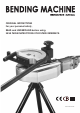
ORIGINAL INSTRUCTIONS For your personal safety, READ and UNDERSTAND before using. SAVE THESE INSTRUCTIONS FOR FUTURE REFERENCE.
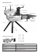
FUNCTIONAL DESCRIPTION Output Spindle Shoe Pivot Bolt Driver Hook Bending Former Bending Shoe Shoe Bracket Direction Lever Trigger Switch LCD screen Brush Cap Gear case Tripod Bending Former & Bending Shoe Voltage Power Input No Load min-1 Max. Capacity Insulation Net Weight 1. 5/8" R=4D 2. 3/4" R=4D 3. 7/8" R=4D 4. 1" R=4D 5. 1-1/8" R=4D 6. 1-1/4" R=4D 7. 1-3/8" R=3.5D See machine nameplate 1700W 3.5 Φ38mm (1-1/2") Double Insulation (Class II) 14kg ( 30.
GENERAL SAFETY INSTRUCTIONS WARNING! Read all safety warnings and all instructions. Failure to follow the warnings and instructions may result in electric shock, fire and/or serious injury. Save all warnings and instructions for future reference. The term “power tool” in the warnings refers to your mainsoperated (corded) power tool or battery-operated (cordless) power tool. e. f. sharp edges or moving parts. Damaged or entangled cords increase the risk of electric shock.
or jewelry. Keep your hair, clothing and gloves away from moving parts. Loose clothes, jewelry or long hair can be caught in moving parts. g. If devices are provided for the connection of dust extraction and collection facilities, ensure these are connected and properly used. Use of dust collection can reduce dustrelated hazards. operations different from those intended could result in a hazardous situation.
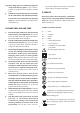
SPECIFIC SAFETY RULES SET UP 1. 1. 2. 3. Keep the working area clear for the bending process. Obstructions could cause a hazard and interfere with the bending process. Do not exceed the maximum pipe diameter a n d wa l l t h i c k n e s s s p e c i f i e d fo r t h i s machine. Use of over-capacity sizes will cause a safety hazard and could damage the machine. Keep the hands away from all moving parts during the bending process.
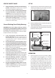
4. Driver Hook Set the Direction Lever to Forward by pushing the lever to the right “F “ position. Bending Former Direction Lever LCD screen 5. NOTE: Whenever the machine is first plugged in always select reverse "R", then press & hold the trigger switch , and it will automatically return to its (zero degree) starting position. the LCD screen will display "0" for a moment, followed by the previous bending angle setting. The machine is now ready to perform the bending operation. 2. Trigger Switch 6.
L=The total length of the pipe before it is bent L 1=The resulting leg length on the end which is bent, measured from the centerline of the pipe. (See diagram) A L1 L2 L1 A L2 L1 A L2 L2=The resulting leg length of the other end of the pipe which is not bent, measured from the centerline of the pipe. (See diagram) L=L1+L2-LM A=L1-LR L=L1+L2 A=L1-LR LR=The reserve length correction. (This is from the chart.
MAINTENANCE All machine repairs should be performed by a qualified repair technician. Every 50 hours of operation blow compressed air through the motor while running at no load to clean out accumulated dust. (If operating in especially dusty conditions, perform this operation more often.) 1. 2. 3. Caution: If the LCD screen is damaged shown “ E1 “, “ E2 “ & “ E3” it must be replaced by the service organization. Error Codes Keep the machine clean and free of dust.
BROWN SWITCH 9 AC BLUE BLACK BLACK BROWN YELLOW RELAY 1 3 2 4 ELECTRONICS UNIT BLACK BROWN BROWN BLUE BLACK RED CARBON MOTOR WIRING
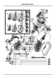
82 81 80 79 78 69-5 69-4 10 76 70 54 55 56 57 69-2 69-3 54 69-1 60 74 37 51 52 37 46 43 47 49 48 39 36 39 42 41 40 39 35 68 63 64 65 66 NO.01~85 A1~A12 V1.
PARTS LIST NO.