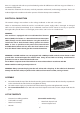
Original instructions CAUTION: Machine equipped with overheat thermal protection. When the t h e r m a l p ro te c t i o n k i c k s i n , always remove from the worpiece and run at no load for at least 3 minutes to allow motor to cool before returning to operation.
Model Power Input Voltage No Load min-1 Capacity (Hand-Held) Arbor Thread Neck Diameter Dimensions Net Weight D-Handle Model D-Handle Model Pistol-Handle Model 110-120V: 1700W, 220-240V: 2000W See machine nameplate 930 / 1520 / 4270 80mm (3") 1-1/4"UNC & 1/2" BSP 60mm 528mm X 106mm X 145mm 437mm X 115mm X 289mm 6.4kg (14 Lbs.
GENERAL SAFETY INSTRUCTIONS WARNING Read all safety warnings and all instructions. Failure to follow the warnings and instructions may result in electric shock, fire and/or serious injury. Save all warnings and instructions for future reference. The term "power tool" in the warnings refers to your mains-operated (corded) power tool. 1) Work area safety a. b. c. Keep work area clean and well lit. Cluttered or dark areas invite accidents.
g. away from moving parts. Loose clothes, jewellery or long hair can be caught in moving parts. If devices are provided for the connection of dust extraction and collection facilities, ensure these are connected and properly used. Use of dust collection can reduce dust-related hazards. 4) Power tool use and care a. b. c. d. e. f. g. Do not force the power tool. Use the correct power tool for your application.
DRILL SAFETY WARNINGS • • • • • • • • • • • • • • • Wear ear protectors when impact drilling. Exposure to noise can cause hearing loss. NOTE The above warning applies only to impact drills and may be omitted for drills other than impact drills. Use auxiliary handle(s), if supplied with the tool. Loss of control can cause personal injury. Hold power tool by insulated gripping surfaces, when performing an operation where the cutting accessory may contact hidden wiring or its own cord.
times. It is equipped with a three speed mechanical gearbox for different core drill size ranges and features a mechanical safety clutch. The motor has electronics for soft start, overload protection and thermal (overheating) protection. There is an indicator light on the machine to alert the operator of load and temperature conditions. ELECTRICAL CONNECTION The network voltage must conform to the voltage indicated on the tool name plate.
OPERATING INSTRUCTIONS 1) MOUNTING THE CORE BIT CAUTION: Ensure that the threads of the spindle and the core bit match. Attempting to mount mismatched threads will result in damage to both threads. The spindle has two types of threads. The outside male thread is 1-1/4inch UNC, the inside female thread is 1/2 inch BSP. Ensure both the core bit and the machine spindle are clean. Any debris could cause excessive run-out of the mounted core bit.
To connect the water supply. Attach the quick-release water coupling to a water hose. WARNING: Never allow water to enter the motor. It could lead to an electric shock. WARNING: Check all connections of the water feed system to ensure there are no leaks. Inspect hoses and other critical parts which could deteriorate. WARNING: The maximum water pressure should not exceed 70 psi (4 bar). CAUTION: There are two small holes on the top of the gearcase.
4) THE SWITCH Lock Button The machine has a lockable trigger switch. Squeeze the trigger to start the machine. To lock the switch on, press the lock button while holding the trigger switch on. To release, squeeze the trigger and release. Trigger Switch WARNING: Never lock the switch on when drilling hand-held. Only lock the switch on when mounted to a rig.
7) DIAMOND CORE DRILLING WARNING: When coring through a floor, the core will fall down. Take precautions to avoid injury or damage below. NOTE: When drilling with a new bit for the first time, use less than normal feed pressure for a time until it breaks-in. 1. Press the “Reset” button on the PRCD interrupter device to energize the circuit to the machine. Then squeeze the trigger switch to turn the machine on.
controlled erosion. The bond matrix holding the diamonds is continually worn away by abrasion with the work piece, exposing the harder diamonds to stand proud from the bond matrix. A bit with good diamond exposure is a sharp bit. This erosion process causes heat and particles, which require water to cool and rinse free. Without adequate water, the bit would overheat and be destroyed.
Another method is to drill into a cinder block. Repeat as needed. If that still does not work the only choice is to use a dressing stone. VIBRATION TROUBLESHOOTING If vibration occurs and it is not caused by embedded steel, stop drilling to find the cause and remedy. CAUTION: Do not operate with vibration or there will be serious hazard and the diamond core bit will surely be destroyed. Vibration is usually caused by: 1. A bit with too much runout SOLUTION: Replace bit. 2.
• • Change the gear oil about every 100 hours of operation Replace the clutch discs and spring as needed. Each year perform a full mechanical inspection, cleaning and re-lubrication. THE CARBON BRUSHES The carbon brushes are a normal wearing part and must be replaced when they reach their wear limit. This machine is equipped with auto-stop carbon brushes. If the machine comes to a stop unexpectedly, the brushes should be checked.
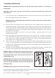
BLACK BLACK BRUSH STATOR BLACK (TEMP.
14 96 17 19 89 07 21 18 22 14 16 93 06 13 90 91 05 15 04 94 09 29 28 25 11 03 26 08 02 15 39 40 01 66 27 42 12 67 44 37 68 69 70 98 OPTIONAL 30 45 95 38 71 49 31 39 50 51 NO.01~99 V1.
D-Handle Model Parts List NO.
16 06 09 01 02 14 15 19 03 17 97 89 21 22 18 11 05 04 18 95 91 92 94 15 90 29 28 25 26 07 13 12 39 NO.01~100 V1.
Pistol-Handle Model Parts List NO.
14 100 17 19 89 07 21 18 22 14 20 93 13 06 90 92 05 15 04 94 09 29 28 25 11 03 26 08 02 15 39 40 01 27 66 42 12 67 44 37 68 69 103 OPTIONAL 30 45 101 38 71 49 31 39 50 51 102 52 85 NO.01~111 Version 2.0 70 46 48 53 32 54 74 86 56 75 84A 76 33 104 84B 77 55A 78 34 59 55B 77 60 79 83 36 35 80 65 82 81 99 98 97 96 95 FOR NO.55A 111 110 108 109 108 108 107 106 105 FOR NO.
Convertible Models: D-Handle Model Parts List NO.
16 06 09 01 02 14 15 19 03 17 100 89 21 22 11 05 04 18 22 94 91 92 15 90 29 28 26 08 07 13 12 39 NO.01~111 Version 1.9 93 25 40 27 42 66 67 44 37 69 103 OPTIONAL 68 30 45 101 38 70 46 48 71 49 39 50 51 31 85 52 102 53 32 54 74 86 56 75 84A 76 33 104 84B 77 59 55B 34 78 55A 77 60 79 83 80 36 35 65 82 81 99 98 97 95 96 FOR NO.55A 111 110 108 109 108 108 107 106 105 FOR NO.
Convertible Models: Pistol-Handle Model Parts List No.