ORIGINAL INSTRUCTIONS FOR YOUR PERSONAL SAFETY, READ AND UNDERSTAND BEFORE USING. SAVE THESE INSTRUCTIONS FOR FUTURE REFERENCE. Warning: Only tools equipped with over load protection, when motor has been cut off due to over load, always switch on machine with no load for at least 3 minutes to reduce temperature before switch on again to avoid burn out to the motor.
Power input Voltage No load min-1 Max. Cutting Capacity Pipe Mounting Capacity Drill Chuck Capacity Over load protection Soft Start Overall Dimensions ( LxWxH) Net Weight 1100W See machine nameplate 130 Φ127mm Φ32-203 mm 1mm-16 mm With Without 319 mm x 270 mm x 302 mm 14.5kg ( 31.
GENERAL SAFETY INSTRUCTIONS WARNING! Read all safety warnings and all instructions. Failure to follow the warnings and instructions may result in electric shock, fire and/or serious injury. Save all warnings and instructions for future reference. The term “power tool” in the warnings refers to your mainsoperated (corded) power tool or battery-operated (cordless) power tool. 1) WORK AREA SAFETY a. b. c. Keep work area clean and well lit. Cluttered or dark areas invite accidents.
d. e. f. g. the switch or energising power tools that have the switch on invites accidents. Remove any adjusting key or wrench before turning the power tool on. A wrench or a key left attached to a rotating part of the power tool may result in personal injury. Do not overreach. Keep proper footing and balance at all times. This enables better control of the power tool in unexpected situations. Dress properly. Do not wear loose clothing or jewelry. Keep your hair, clothing and gloves away from moving parts.
Symbol Name Designation/Explanation V Volt Voltage (potential) A Amperes Current Hz Hertz Frequency (cycles per second) W Watt Power kg Kilograms Weight min Minutes Time s Seconds Time ø Diameter Size of drill bits n0 No load speed Rotational speed, at no load min-1 Revolutions per minute Revolutions, strokes, surface speed per minute.
HOLE CUTTING MACHINE INSPECTION Inspect your hole cutting machine periodically to prevent malfuntion and potential accident from happening. 1. 2. 3. 4. 5. Check for functionality of the switch, do not operate a tool that can not be controlled by switch. Inspect the power cord, ground prong, and plug carefully for any damage. Always make sure the cord is intact before performing any operation, fail to comply might leads to electric shock! Clean scrap, grease or dirt after every use.
user’s need. If it is required to mount the crank lever on the opposite side or to change its position, push the Release Button in the center of the Crank Hub and remove. Press the Button and mount on the opposite side or in the desired position. Start hole cutting by pushing green button ON. On/off switch STEEL SCRAP WILL BECOME HOT AFTER HOLE CUTTING PROCESS, DO NOT TOUCH THE STEEL SCRAP IMMEDIATELY AFTER CUTTING! After finished hole cutting, push red button OFF to stop the hole cutting machine.
SWITCH OFF THE MACHINE IMMEDIATELY AFTER USE TO PREVENT ACCIDENT OR OPERATE BY UNTRAINED PERSONNEL! MAINTENANCE Every 50 hours of operation blow compressed air through the motor while running at no load to clean out accumulated dust. (If operating in especially dusty conditions, perform this operation more often.) Clean scrap after every use and make sure frictional metal parts are well lubricated to prevent rusty! THE ARBOR SHAFT Keep the arbor shaft free of dirt and lightly grease as needed.
SWITCH AC 9 CARBON BRUSH CARBON BRUSH MOTOR EMC UNIT WIRING
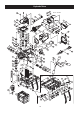
Exploded View 94 06 NO.01~101 V2.
Parts list NO. 1 2 3 4 5 6 7 8 9 10 11 12 13 14 15 16 17 18 19 20 21 22 23 24 25 26 27 28 29 30 31 32 33 34 35 36 37 38 39 40 41 42 43 43 44 45 46 47 48 48 49 Parts Name INTERNAL CIRCLIP R-40 PARALLEL KEY 5 x 5 x 10 SPINDLE 5/8"-16 BEARING 6203-2NSE EXTERNAL CIRCLIP S-17 SCREW M5 x 25 GEAR CASE OUTPUT GEAR M1.5 x 44T EXTERNAL CIRCLIP S-15 BEARING 6200 zz INTERMEDIATE GEAR PINION M1.5 x 9T INTERMEDIATE GEAR M1.