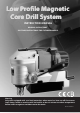
Low Profile Magnetic Core Drill System INSTRUCTION MANUAL ORIGINAL INSTRUCTIONS SAVE THESE INSTRUCTIONS FOR FUTURE REFERENCE. Warning: Only tools equipped with over load protection, when motor has been cut off due to over load, always switch on machine with no load for at least 3 minutes to reduce temperature before switch on again to avoid burn out to the motor.
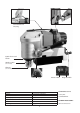
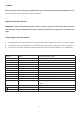
Good balance for Carrying Crank Lever Quick-release tool holder Annular cutter (Not included) Pilot pin (Not included) LED Work Light Power Input Voltage No Load / Full Load min-1 Max. Capacity Dia. X Depth of cut Magnetic Adhesion Dimensions Net weight 1100W See machine nameplate 650 / 390 35mm x 35mm (1-3/8" x 1-3/8") 15,000 N 285 x 101 x 200mm 10kg (22.
GENERAL SAFETY INSTRUCTIONS WARNING! Read all safety warnings and all instructions. Failure to follow the warnings and instructions may result in electric shock, fire and/or serious injury. Save all warnings and instructions for future reference. The term “power tool” in the warnings refers to your mainsoperated (corded) power tool or battery-operated (cordless) power tool. 1) WORK AREA SAFETY a. Keep work area clean and well lit. Cluttered or dark areas invite accidents. b.
moment of inattention while operating power tools may result in serious personal injury. b. Use personal protective equipment. Always wear eye protection. Protective equipment such as dust mask, non-skid safety shoes, hard hat, or hearing protection used for appropriate conditions will reduce personal injuries. c. Prevent unintentional starting. Ensure the switch is in the off-position before connecting to power source and/or battery pack, picking up or carrying the tool.
) SERVICE Have your power tool serviced by a qualified repair person using only identical replacement parts. This will ensure that the safety of the power tool is maintained. Symbols used in this manual IMPORTANT: Some of the following symbols may be used on your tool. Please study them and learn their meaning. Proper interpretation of these symbols will allow you to operate the tool better and safer. Terminology used in the manual 1.
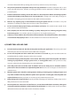
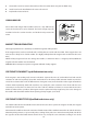
SPECIFIC SAFETY RULES AND REGULATIONS WARNING: For your own safety, never use coolant containing water while operating at more than a 90 degree from horizontal. Spray-type coolant which do not contain any ingredient of water should be used ! Always use safety chain. Mounting can release. The magnet’s adhesion depends on the thickness of the work piece. Always ensure that the work piece is a minimum of 12mm (7/16 in.) thick.
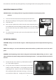
thread the loose end of the strap through the loop and pull tight. Push on the spring buckle to release strap. MOUNTING ANNULAR CUTTERS CAUTION: Never use a cutting tool that is larger than the maximum rated capacity of the machine. 1. To insert an annular cutter, first insert the pilot pin into the cutter. 2. Whenever mounting or removing cutters, always unplug the machine. 3. Lower the arbor. 4. Push up on the quick-release collar.
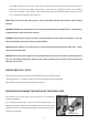
pace. With experience, the operator will be able to determine the best pace to feed to the work. There should be some degree of audible slowing of the motor but not bogging in the cut. Correct cutting speed with a properly sharp annular cutter will produce long unbroken chips, which produce a “bird’s” nest. shaped bundle of chips around the cut. NOTE: Always ensure that the cutting tool is sharp. A dull cutter typically will have finer and/or choppy shavings.
THE OPTIONAL LED WORK LIGHT Models equipped with the optional LED WORK LIGHT have a light which is always on whenever the machine is plugged in. This can be useful when working in dark work spaces. LED Work Light CAUTION: Never attempt to re enter a half-finished cut if the magnet has been turned off and the machine shifted in the interim. This may destroy the cutter. MAINTENANCE Every 50 hours of operation blow compressed air through the motor while running at no load to clean out accumulated dust.
3. Unscrew the screw to remove the brush lead. The old carbon brush may now be lifted away. 4. Install a new brush. Installation is the reverse of removal. 5. Replace the motor tail cover. CARBON BRUSHES Due to the brush design, if the machine comes to a stop without any reason, the brushes have to be checked. The brush design stops the machine before the carbon brushes are finished and protects the motor.
circuits has zero resistance, it means that it is shorted. If one of the circuits has infinite resistance, it means that the circuit is broken. If the replacement of the power supply cord is necessary, this has to be done by the manufacturer or their agent in order to avoid a safety hazard. WARNING: All repairs must be entrusted to an authorized service center. Incorrectly performed repairs could lead to injury or death.
Wiring (230V) (110V) MAGENT MAGENT BLACK RED RED RED BLACK BLACK + BLACK RED A - - A B C + D D MOTOR SWITCH YELLOW YELLOW BLACK 13 GEAR CASE 14 MOTOR A 23 24 B BLACK C LED LAMP D MAGNET SWITCH RECTIFIER & EMC EARTH BLUE AC BLUE 13 GREEN
10 11 12 13 14 15 01 02 92 03 04 08 09 16 17 18 19 104 105 106 05 06 07 87 230V 88 86 102 86 102 110V 230V 110V 86 85 85 19 79 47 76 87 28 29 78 88 86 72 46 21 22 23 20 30 80 24 59 60 77 58 57 81 24 27 26 25 32 31 68 109 75 68 73 67 45 58 61 33 46 47 93 19 66 68 71 49 70 35 NO.01~114 V3.
Parts list NO. 1 2 3 4 5 6 7 8 9 10 11 12 13 14 15 16 17 18 19 20 21 22 23 24 25 26 27 28 29 30. 31 32 33 34 35 36 37 38 39 40 41 42 43 44 45 46 47 48 49 50 51 52~54 55 56 Parts Name INTERNAL CIRCLIP R-19 ARBOR WASHER ø10 x ø18.5 x 0.8 COOLANT SEAL ø10.2 x ø12 x 15 SPRING ø1.2 x ø10 x ø12.4 x 7T x 54L LOCK PIN 12.3mm ,11.