
Owner`s manual


3
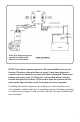
Route heavy gauge wire from battery to tarp motor. Allow ample wire where
cutting and mounting connections take place. SEE Figure 1, box with hoist
and Figure 2, semi-trailer box, on page 4. Prepare wire ends for terminals,
heat shrink tubes and rubber boots.
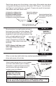
Mount receiver to a rigid location at least 4
feet away from motor and other danger. With
terminals pointed down, use control box as
template to mark hole drilling locations. Use
bolts, nuts and washers to nish
mounting. Attach heavy gauge
wires to terminals on control box
as shown. Slide rubber boots over
terminals.
Attach heavy gauge wire to circuit breaker
as shown near positive post on battery.
Remember to seal with heat shrink rst
and slip wires through rubber circuit
breaker cover (not shown).
When on new tarp install attach tarp caution/operating decal to front
driver side corner of truck box.
1/2 Eyelet For (+) Battery Post
3/8 Eyelet For (-) Battery Post
5/16 Eyelet For Motor Terminals
#10 Eyelet For Circuit Breaker
1/4 Eyelet For Control Box Terminals
Typical Heat Shrink Tube
For All Heavy Gauge Wire
Connections
Rubber Terminal Boots For
Control Box Connections Only
Typical For All Heavy
Gauge Wire Eyelets
Black Motor 1
Red Motor 2
Black –
Install Box
With Terminals
Pointing Down.
Red +
Battery
Aux.
This Red Striped Wire
to Control Box (+)
This Red Striped
Wire to Battery (+)
Circuit Breaker
NOTE: Always hold base nuts
when tightening top nuts on
terminals.
IMPORTANT: Make sure
system has a 50 amp
modied reset circuit
breaker installed as shown.
STEP 2
STEP 3
STEP 4
NOTE: If kit came pre-wired with 40 Amp breaker, remove it and
use 50 Amp breaker supplied loose in Command-10
®
kit.