Installation Manual ROLTECTM ELECTRIC HOPPER CONVERSION Thank you for purchasing a ROLTECTM Electric Hopper Conversion system. ACI has manufactured this product with pride using superior quality materials and strict quality control manufacturing processes. NOTICE TO INSTALLER: It is recommended you take the time to read these instructions carefully before installing or using this Electric Hopper Conversion. Often improvements are made without prior notice.
Inspection and Maintenance • Periodic preventive maintenance should be practiced. Inspect system often for proper operation. • Periodically inspect all components for loose or worn parts and replace as needed. • Always use genuine Agri-Cover, Inc. replacement parts if repairs are needed. • Periodically check the tightness of mounting bolts and electrical connections. Remove any dirt or corrosion that may have accumulated on the electrical connections. • Do not attempt to disassemble the motor.
Table of Contents Inspection, Maintenance and Safety..................................................Page 2 Tools for Installation............................................................................Page 3 Part Numbers and Diagrams..............................................................Page 4-7 Installing Roltec Conversion...............................................................Page 8-15 Installing Electrical Parts....................................................................
Part Numbers and Descriptions (item numbers are used to reference parts in diagrams throughout this manual) Item 1 2 3 4 5 6 7 8 9 10 11 12 13 14 15 16 17 18 19 20 Part # 80210 80220 80230 80240 Description Electric Hopper Conversion (1 Conversion) Electric Hopper Conversion (2 Conversions) Electric Hopper Conversion (3 Conversions) Electric Hopper Conversion (4 Conversions) 80108 80222 80163 10921 10922 80091 80065 80194 80196 80160 80147 80186 80081 80153 80187 10893 10186 10903 10185 80162 80155 Se
ROLTECTM Electric Hopper Conversion Parts Diagram 18 17 16 17 18 15 19 16 15 14 9 13 8 5 4 4 2 3 6 3 10 7 4 12 1 20 11 5
Part Numbers and Descriptions (item numbers are used to reference parts in diagrams throughout this manual) Item 1 2 3 Part # 80239 80207 80235 Description Wireless Control Box Remote Key Fob w/ Lanyard Bolt, 1/4” x 1-3/4’ GR 5, Zinc Plated 4 5 6 7 8 9 10 11 12 13 14 15 16 17 30212 30623 30625 60598 30650 70278 20046 60496 80197 10893 10185 10903 10186 80146 Washer, Flat 1/4”, Zinc Plated Washer, Lock 1/4”, Zinc Plated Nut, 1/4” hex, Zinc Plated Eyelet Terminal Ring, 1/4” Heat Shrink Terminal boots, L
ROLTEC® Electric Hopper Conversion Electric Parts Diagram Shown Separate for Diagram Only, Comes Pre-Assembled in Control Box 13 12 2 Wire To Motor 9 14 8 7 15 16 3 17 1 10 10 9 8 7 7 8 9 8 4 5 6 11 Wire To Dual Pole Connector Semi Trailer Kit with Dual Pole Connector (Included in Part Number 80108) 20 18 25 19 21 24 22 23 26 7
STEP 1 NOTE: Prior to installing electric hopper conversion, perform all necessary maintenance on hopper doors. Hold drive box on crank shaft to determine best location for motor based on ability to mount the anchor brace to a solid location. Motor assembly must be square to shaft. NOTE: Mounting tab on Anchor Brace may need to be bent to ensure proper connection.
STEP 3 Between two additional marks made in previous step, clean shaft to bare metal for welding and to insure overall diameter is 1”. NOTE: Ensure shaft is clean at location of polyethylene bushing assembly. Once shaft is clean replace 1st mark (documented in Step 2) back on shaft, place set collar on outside of mark and secure to shaft with 3/16” Allen Wrench.
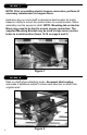
STEP 5 Clamp sprocket assembly to set collar to ensure sprocket stays square to drive shaft. Sprocket Assembly Set Collar Hopper Crank Weld This Side In Next Step Figure 5 STEP 6 Weld sprocket assembly to drive shaft and let cool. Check sprocket teeth for weld splatter, deburr if necessary.
STEP 7 Loosen set collar and either remove from shaft or move it out of the way. Sprocket Assembly Welded To Shaft Move Or Remove Set Collar To Be Used Later Figure 7 STEP 8 After sprocket assembly and shaft are cool to the touch place motor assembly back on shaft, insert second half of polyethylene bushing and secure to motor assembly with lock washer and nuts.
STEP 9 Move set collar tight against plastic bushing to square up motor and secure in place by tightening set screws, motor assembly will spin freely on the shaft. Move Set Collar Figure 9 STEP 10 Slide anchor brace into motor assembly. Mounting tab may need to be bent to ensure a flat or secure fit at mounting location (Figure 10a).
The supplied Mounting Bracket may be used to help secure anchor brace to a solid location (Figure 10b). Secure Mounting Location Underside Of Trailer 3/8” x 1” Bolt 3/8” Nut Mounting Bracket 3/8” Lock Washer Anchor Brace 3/8” Washer Figure 10b Mark and cut off excess brace material (Figure 10c).
STEP 11 Mark location of mounting tab on trailer, drill 5/16” hole and secure brace with 3/8” self threading bolt and back it with flat washer, lock washer, and nut where possible. 3/8” Self Threading Bolt Figure 11 STEP 12 Place chain on sprockets, chain has two master links to ensure chain can be changed in any location of motor. Master links should be installed so clip is visible. The motor is used as the chain tensioner.
STEP 13 Attach chain cover with wing nut and lock washer.
STEP 14 Attach Gearbox cover plate over shaft and insert tabs into slots in housing. Secure with stainless steel hair cotter pin.
STEP 15 PREPARE WIRING FOR CONNECTOR TERMINALS. The illustration below shows terminal ring sizes for heavy gauge wires connecting to battery posts, circuit break, and motor terminals used in the following steps. Insulation is stripped off ends, heat shrink tubes are supplied for sealing and rubber boots are supplied for control box terminals. Always measure wire lengths to ensure you have plenty of wire when cutting and attaching terminals.
STEP 16 NOTE: If installing on trailer with existing electric tarp skip to step 17. ELECTRIC WIRE ROUTING A. Dual Pole Connector – Mount plug connector to suitable location on semi-tractor, adjacent to existing plugs. Mount socket to suitable location on trailer. Prep wires by stripping off insulation as needed. On wires at socket, slide heat shrink tube over wire, attach ring terminals and apply heat to shrink tubes. Bolt terminals tight.
STEP 17 Note: Remote will come pre-programmed from the factory. Remote control boxes will come numbered from factory to coincide with function of remote each box has been programmed to. Refer to Command-10 owner’s manual or the remote programming video at www.agricover.com/rolltarps/videos for re-programming and directions to program multiple remotes and receivers. A. Attach remote control box bracket to a rigid location on trailer near electric hopper motor.
STEP 18 Run heavy gauge wire from remote control box to electric motor terminals. Prepare wire ends for motor terminals with heat shrink tubes, 5/16” ring terminals, and rubber boots. Attach BLACK wire to terminal 1 on motor. Attach RED wire to terminal 2. Always hold base nut while tightening top nut. At Battery, first attach RED wire to (+) positive post. Then attach BLACK wire to (-) negative post. Check power by activating switch to open position and closed position.
STEP 19 WIRING ADDITIONAL ELECTRIC HOPPER BOTTOMS A. Attach remote control box bracket to a rigid location on trailer near electric hopper motor. Align remote control box, terminals down, with pre-drilled holes in bracket. Secure using bolts, washers, and nuts provided. B. Select most suitable route for wires usually along frame with existing harness. Run heavy gauge wire from first remote control box to second remote control box. Prep wires by stripping off insulation as needed.
WIRING ADDITIONAL ELECTRIC HOPPER BOTTOMS Dual Pole Connection Bat (-) Black Bat (-) Black Bat (+) Red Aux 40 AMP Breaker From Control Box 1 Bat (+) (-) Black Heavy Gauge Wire (+) Red REMOTE CONTROL BOX 1 BATTERY Black Motor 1 Heavy Gauge Wire Red Motor 2 REMOTE CONTROL BOX 2 (+) Red Heavy Gauge Wire (-) Black Red Motor 2 MOTOR 1 Note: Use dielectric grease (packet included) at all electrical connections.
Electric Hopper conversion kits will come with 2 arrow decals (PN 80489) per hopper bottom. Decals are provided to aid operator in opening and closing hopper doors. Place decal on side of hopper when gate is at both fully open and fully closed positions (see image below). NOTE: Location may very depending on trailer manufacturer, may not be applicable on some trailers. Arrow Decals TO ENABLE MANUAL OVERRIDE: 1. Disconnect Power to hopper motor. 2.
MANUFACTURER’S LIMITED WARRANTY Agri-Cover, Inc. extends the following limited warranty on its ROLTEC® ELECTRIC HOPPER CONVERSION to the original retail purchaser: Agri-Cover, Inc. warrants its ROLTEC® ELECTRIC HOPPER CONVERSION to be free from defects in material and workmanship under normal use for one (1) year from date of manufacture unless accompanied by proof of purchase.