OWNERS MANUAL Model No. 45-02102 125 LB. PUSH BROADCAST SPREADER CAUTION: Read Rules for Safe Operation and Instructions Carefully Assembly Operation Maintenance Repair Parts PRINTED IN U.S.A. FORM NO. 48313 (REV.
RULES FOR SAFE OPERATION The following safety precautions are suggested. This broadcast spreader is designed, engineered and tested to offer reasonably safe and effective service, provided it is operated in strict accordance with these instructions. Failure to do so may result in personal injury. Always observe the rules of safe operation. 3. Wear eye and hand protection when handling and when applying lawn or garden chemicals. 4.
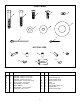
FULL SIZE A B E D C H F G J I NOT FULL SIZE K P N M L O R Q HARDWARE PACKAGE KEY QTY. A B C D E F G H I 6 2 2 1 10 6 4 4 1 KEY QTY. DESCRIPTION J K L M N O P Q R Hex Bolt, 1/4-20 x 1-3/4" Long Hex Bolt, 1/4-20 x 1-1/2" Long Hex Bolt, 1/4-20 x 3/4" Long Carriage Bolt, 1/4-20 x 3/4" Long Hex Lock Nut, 1/4-20 Thd.
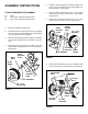
ASSEMBLY INSTRUCTIONS 5. Place the short spacer tube and a 3/4" washer onto the end of the axle that has the large drilled hole (left hand side). See Figure 2. TOOLS REQUIRED FOR ASSEMBLY 6. (1) (2) (3) Place the drive wheel onto the axle. The notched hub and the air valve should face to the outside. See Figure 2. 7. Fasten the wheel to the axle using a 1/4" x 1-3/4" hex bolt and a 1/4" hex lock nut. See Figure 2. Pliers 7/16" Open or Boxed End Wrenches 9/16" Open or Boxed End Wrenches 1.
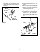
IMPORTANT: Do Not assemble long handle tube on same side of crossover tube as shaft support plate. Assemble on opposite side. 9. 13. Assemble the leg stand tube to the long handle tube using two 1/4" x 1-1/2" hex bolts. Secure tightly with two 1/4" hex lock nuts. See figure 5. 14. Place a vinyl cap onto the end of the leg stand tube. See figure 5. Place the long handle tube onto the crossover tube on the opposite side from the shaft support plate.
16. Assemble the flow control arm to the flow control mounting bracket using a 1/4" x 3/4" hex bolt, two nylon washers and a 1/4" hex lock nut as shown in figure 7. Tighten carefully. The flow control arm should be snug, but should pivot with no more than a slight resistance. 17. Assemble the vinyl grip. See figure 7. 19. Hook free end of flow control rod through hole in slide gate bracket located near bottom of hopper. See figure 9.
22. Place the adjustable stop into the "ON" end of the slot in the top of the flow control mounting bracket. Secure with the 1/4" x 3/4" carriage bolt, a nylon washer, a 5/16" flat washer and the nylon wing nut. See figure 11. 23. Position the flow control mounting bracket (Refer to figure 12). a. Push on flow control arm until it locks in "OFF" position. b. Slide flow control mounting bracket along tube until closure plate in bottom of hopper just closes. c.
11. Heavy moisture conditions may require a cover over the hopper to keep contents dry. The vinyl cover (available as an accessory) acts as a wind and moisture shield, but should not be used as a rain cover. Refer to the parts list on page 11. OPERATION HOW TO USE YOUR SPREADER SETTING THE FLOW CONTROL (Refer to figure 12 on page 7.) 1. 2. 3. Loosen the nylon wing nut, set the adjustable stop to the desired flow rate setting and retighten the wing nut.
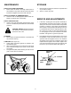
MAINTENANCE STORAGE CHECK FOR LOOSE FASTENERS 1. Before each use make a thorough visual check of the sreader for any bolts and nuts which may have loosened. Retighten any loose bolts and nuts. 1. 2. CHECK FOR WORN OF DAMAGED PARTS 2. Check for worn or damaged parts before each use. Repair or replace parts if necessary. Rinse inside of hopper and exterior of spreader and dry off before storing. Store in a clean, dry area. SERVICE AND ADJUSTMENTS CHECK TIRE INFLATION 3.
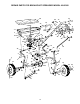
REPAIR PARTS FOR BROADCAST SPREADER MODEL 45-02102 64 52 37 13 40 16 39 37 40 39 8 9 2 7 48 44 11 1 C 7 54 55 32 31 39 5 9 33 38 27 40 9 10 35 18 E D 53 7 7 A 57 56 7 34 49 28 36 59 18 19 7 17 9 15 61 20 20 21 24 22 C 45 47 50 46 60 41 42 B 11 39 6 32 D 9 A 9 51 11 4 9 40 9 58 30 3 53 25 26 14 12 32 4 43 E 62 B 9 62 35 22 9 9 10 23 62 63
REPAIR PARTS FOR BROADCAST SPREADER MODEL 45-02102 REF. NO. PART NO. QTY. 1 2 3 4 5 6 7 8 9 10 11 12 13 14 15 16 17 18 19 20 21 22 23 24 25 26 27 28 29 30 31 32 33 34 35 36 44466 43882 62482 44462 23753 23758 1509-69 24857 43013 43808 43012 44566 44463 44457 44456 44464 23752 43851 43871 1540-32 1540-162 47615 44494 44450 23524 04367 43850 44465 C-9M5732 23766 43878 43088 44468 44514 23525 23762 1 4 1 1 1 1 12 1 18 1 3 1 1 1 1 1 1 2 1 5 1 2 1 1 1 1 1 1 2 1 1 13 1 1 2 1 REF. NO.
AGRI-FAB ® LIMITED WARRANTY WHO IS COVERED: This Warranty covers only the original retail purchaser of an AGRI-FAB ® product or part. It is not transferable. HOW LONG DOES COVERAGE LAST: This Warranty remains in force for 1 year from the date of purchase. WHAT IS COVERED: Any defect in material or workmanship of your AGRI-FAB ® product or part. WHAT IS NOT COVERED: 1. This warranty does not apply to the engine or components parts thereof.