™ APPLICATIONTIPS xxxxxxxxxxxxxxx xxxxxxxxxxxxxxxxxxxxxx xxxxxxxxxxxxxxxxxxxx xxxxxxxxxxxxxxxxxxxxxx xxxxxxxxxxxxxxxxxxxxx xxxxxxxxxxxxxxxxxxxxxx xxxxxxxxxxxxxxxxxxx xxxxxxxxxxxxxxxxxxxxxx owners manual xxxxx xxxxx xxxxxxxxxxxxxxxx xxxxx xxxxx xxxxx xxxxxx xxxxxx xxxxxx xxx xxx xxx xxxxxx xxxxx xxxxxx Model No. 45-02153 100 LB.
RULES FOR SAFE OPERATION Any power equipment can cause injury if operated improperly or if the user does not understand how to operate the equipment. Exercise caution at all times when operating equipment. • • • • • Read the towing vehicle owners manual and towing vehicle safety rules. Know how to operate your tractor before using the broadcast spreader attachment. Read the chemical label instructions and cautions for handling and applying the chemicals purchased for spreading.
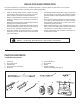
SHOWN FULL SIZE B A C F E D H G J I NOT SHOWN FULL SIZE K REF QTY A 5 B L N M DESCRIPTION REF QTY DESCRIPTION Hex Bolt, 1/4-20 x 1- 1/2" I 1 Hair Cotter Pin 4 Hex Bolt, 1/4-20 x 1" J 1 Hitch Pin C 1 Carriage Bolt, 1/4-20 x 3/4" K 2 Spacers D 9 Nylock Nuts, 1/4-20 L 1 Nylon Wing Nut E 4 Nylon Washer M 1 Adjustable Stop F 8 Flat Washer, 5/16" N 1 Flow Control Link G 1 Cotter Pin, 3/32" x 3/4" O 1 Grip H 3 Flat Washers 1/2" P 2 Hub Cap 3 O P
ASSEMBLY INSTRUCTIONS 6. Assemble the two hitch braces to the hitch tube using a 1/4" x 1-1/2" hex bolt and a 1/4" nylock nut. See figure 2. Do not tighten at this time. TOOLS REQUIRED FOR ASSEMBLY (1) Pliers (2) 7/16" Open or Box End Wrenches (2) 1/2" Open or Box End Wrenches (1) Small Hammer MIDDLE BOLT 1. Remove the spreader, loose parts and hardware package from the carton. Lay out all parts and hardware and identify using the illustrations on pages 2 and 3.
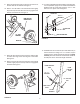
9. Place the wheel (long end of hub first) onto the end of the axle that has no indents. See figure 4. 13. In order to assemble the hitch bracket to the hitch tube, turn the spreader upright on its wheels. Assemble the bracket to the top of the hitch using two 1/4" x 1" hex bolts and 1/4" nylock nuts. See figure 6. 10. Place a 1/2" flat washer onto the axle and then lightly tap a hub cap onto the axle until it is snug against the washer and wheel hub. See figure 4.
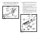
15. Assemble the flow control arm to the flow control mounting bracket using a 1/4" x 1" hex bolt, two nylon washers and a 1/4" nylock nut as shown in figure 8. Tighten carefully. The flow control arm should be snug, but should pivot with no more than a slight resistance. 16. Assemble the vinyl grip. See figure 8. 18. Hook the free end of the flow control rod through the hole in the slide gate bracket located near the bottom of the hopper. See figure 10.
20. Place the adjustable stop into the "ON" end of the slot in the top of the flow control mounting bracket. Secure with the 1/4" x 3/4" carriage bolt, a nylon washer, a 5/16" flat washer and the nylon wing nut. See figure 12. 21. Position the flow control mounting bracket (figure 13). a. Push on flow control arm until it locks in "OFF" position. b. Slide flow control mounting bracket along tube until closure plate in bottom of hopper just closes. c.
OPERATION HOW TO USE YOUR SPREADER REFER TO CHARTS SETTING THE FLOW CONTROL (Refer to figure 13 on page 7.) 1. Loosen the nylon wing nut, set the adjustable stop to the desired flow rate setting and retighten the wing nut. The higher the setting number, the wider the opening in the bottom of the hopper. 2. Refer to the application chart on page 8 and to the instructions on the fertilizer bag to select the proper flow rate setting. 3.
MAINTENANCE SERVICE AND ADJUSTMENTS CHECK FOR LOOSE FASTENERS 1. Before each use make a thorough visual check of the spreader for any bolts and nuts which may have loosened. Retighten any loose bolts and nuts. REPLACING SLOTTED GEAR 1. If the axle, slotted gear and sprocket assembly is disassembled, mark down the positions of the parts as they are removed.The drive wheel and sprocket positions in relation to the slotted gear determine which direction the spreader plate will spin.
REPAIR PARTS FOR BROADCAST SPREADER MODEL 45-02153 30 15 4 1 A 12 31 40 5 39 9 13 40 9 9 50 11 33 7 3 2 40 26 A 27 4 9 11 E B 9 25 B D 40 9 10 19 34 46 12 11 28 35 6 36 33 42 45 21 18 43 20 21 22 32 D 17 9 14 47 22 9 8 39 7 9 11 35 50 39 32 32 E 22 44 37 32 7 23 48 22 24 19 9 24 23 11 49 16 10 9 39 32 41 38 7
REPAIR PARTS FOR BROADCAST SPREADER MODEL 45-02153 REF 1 2 3 4 5 6 7 8 9 10 11 12 13 14 15 16 17 18 19 20 21 22 23 24 25 26 PART NO. QTY DESCRIPTION REF 44624 1 Hopper 27 46055 1 Pin, Spring 1/8" Dia. x 1" Lg. 28 62482 1 Ass'y, Guide Closure 29 40469 1 Tube, Frame 30 23753 1 Slide Gate Angle Bracket 31 23758 1 Slide Gate Bracket 32 43661 5 Bolt, Hex 1/4-20 x 1" Lg. * 33 24857 1 Flow Control Link 34 47189 22 Nylock Nut, 1/4-20 35 44591 1 Tube, Crossover 36 43648 9 Bolt, Hex 1/4-20 x 1-1/2" Lg.
the fastest way to purchase parts www.speedepart.com REPAIR PARTS Agri-Fab, Inc. 303 West Raymond Sullivan, IL. 61951 217-728-8388 www.agri-fab.com This document (or manual) is protected under the U.S. Copyright Laws and the copyright laws of foreign countries, pursuant to the Universal Copyright Convention and the Berne convention.