™ owners manual MANUAL DEL USUARIO NOTICE D’UTILISATION Model No. Modelo No. Modèle No. th mi Ro cks ros Ae 45-03201 42" LAWNSWEEPER BARREDORA DE CESPED DE 106 cm BALAYEUSE DE PELOUSE 106 cm CAUTION: Read Rules for Safe Operation and Instructions Carefully PRECAUCION: Lea cuidadosamente los Procedimientos e Instrucciones para la Operación Segura de la Máquina. ATTENTION: Lire et suivre attentivement les instructions et consignes de sécurité de cette notice.
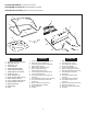
CARTON CONTENTS (Loose Parts in Carton) CONTENIDO DE LA CAJA (Partes Sueltas en la Caja) CONTENU DU CARTON (Pièces en Vrac Dans le Carton) 11 10 10 9 12 11 2 12 1 13 14 3 15 6 16 7 2 4 8 ESPAÑOL ENGLISH 1. 2. 3. 4. 5. 6. 7. 8. 9. 10. 11. 12. 13. 14. 15. 16. Sweeper Housing Assembly Bag Arm Tube (2) Hitch Tube, L.H. Hitch Bracket Hitch Bracket (Straight) Height Adjustment Strap Height Adjustment Handle Hitch Tube, R.H.
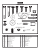
ENGLISH SHOWN FULL SIZE A B D C E F G O P M K N Q R L I S J T U NOT SHOWN FULL SIZE V ref A B C D E F G I J K L M N qty 2 2 4 1 2 1 4 4 11 4 1 1 8 W Y X description Hex Bolt, 5/16 x 2-1/2" Lg. Hex Bolt, 5/16 x 2" Lg. Carriage Bolt, 5/16" x 1-1/2" Hex Bolt, 5/16 x 1-1/4" Lg.
ENGLISH SAFETY RULES Remember, any power equipment can cause injury if operated improperly or if the user does not understand how to operate the equipment. Exercise caution at all times when using power equipment. 6. Vehicle braking and stability may be affected with the attachment of this sweeper. Do not fill sweeper to maximum capacity without checking the capability of the towing vehicle to safely pull and stop with the sweeper attached. Stay off of steep slopes. 1.
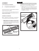
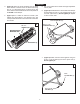
ENGLISH ASSEMBLY IMPORTANT: The overlap bristles at the bottom of each brush help support the back side of the brush for better sweeper performance. Be sure the sweeper is turned as shown in figures 2 and 3 to correctly assemble the brushes. TOOLS REQUIRED FOR ASSEMBLY (2) (2) 7/16" Open End or Box End Wrenches 1/2" Open End or Box End Wrenches 2.
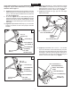
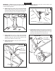
ENGLISH 3. (Figure 3) Attach the brush assembly with the black brush retainer to the left end of the brush shaft using two 1/4" x 1" hex bolts (G) and 1/4" nylock nuts (I). The brush retainer marked with black ink must be placed to the middle of the sweeper. 5. Cut off the plastic tie that holds the height adjustment tube in place. 6. (Figure 4) Assemble the R.H. hitch tube to the sweeper housing using two 5/16" x 1-1/2" carriage bolts (C), and two 5/16" nylock nuts (J). Do not tighten yet.
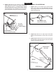
ENGLISH If your tractor hitch has 10" to 13" ground clearance refer to figure 6. If your tractor hitch has 8" to 10" ground clearance refer to figure 7. 11. (Figure 8) Assemble the height adjustment handle to the inside of the bracket on the end of the height adjustment tube. Use two 5/16" x 1" hex bolts (E), 5/16" flat washers (K) and 5/16" nylock nuts (J). Tighten. 12. (Figure 8) Assemble the grip (W) onto the height adjustment handle. 8.
ENGLISH ASSEMBLY OF HOPPER BAG 14. (Figure 10) Place the star washer (L) between the height adjustment handle and the height adjustmenet strap. Insert the 5/16" x 1" carriage bolt (F) through the height adjustment handle, the star washer and the height adjustment strap. Assemble a 5/16" flat washer (K) and the plastic knob (X) onto the end of the bolt. 1. (Figure 11) Turn a rear hopper tube so that the brace holes in the middle of the tube face down.
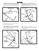
ENGLISH 4. (Figure 13) Turn the second rear hopper tube so that the brace holes in the middle of the tube face up. Assemble the ends of the rear hopper tube onto the ends of the lower hopper side tubes. Fasten together using plastic plugs (Z). REAR HOPPER TUBE (brace holes on top) 7. (Figure 15) Insert the bag frame strap into the stitched sleeve along the front edge of the bag bottom. 8.
ENGLISH IMPORTANT: Do not over bend the support rods during the following step. Over bending will cause the steel rods to loose supporting tension. 13. (Figure 19) Secure the rope to the top center of the hopper bag frame. 19 10. (Figure 17) Tip the hopper onto it's back to assemble the two hopper support rods. Place the ends of each rod into the upper and lower rear hopper tubes, bending the rod just enough to fit into the holes in the tubes. 17 SUPPORT RODS 14.
ENGLISH ATTACHING SWEEPER HITCH TO TRACTOR 21 (Figures 21, 22, 23) 1. Place the tractor and sweeper on a flat level surface. 2. Set the sweeper height adjustment handle to about the middle of its adjustment range. 3. Attach the sweeper hitch brackets to the tractor hitch, arranging the 3/4" spacers so that the bottom of the sweeper bag is approximately level and 5" to 7" above the ground. See figure 22 for tractor hitches that are 10" to 13" above the ground.
ENGLISH OPERATION 4. (Figure 24) Lubricate the brush shaft bearing twice a year with a few drops of light weight oil. HOW TO USE YOUR SWEEPER HEIGHT ADJUSTMENT SLOT BRUSH HEIGHT ADJUSTMENT To adjust your sweeper brushes to the best operating height, loosen the adjustment knob and push down on the height adjustment lever to raise the brush. Best adjustment is when the brush setting is 1/2" down into the grass. Always mow the grass to an even height before sweeping.
ENGLISH SERVICE AND ADJUSTMENTS WHEEL GEAR AND PAWL SERVICE BRUSH REPLACEMENT IMPORTANT: Do not remove both wheels at the same time to avoid mixing of parts. (The R.H. and L.H. ratchet gears are not interchangeable.) Make notes on the position of washers and snap rings during disassembly. NOTE: Brush replacement should be done one brush at a time. 1. Remove only one wheel from the sweeper. 2. Remove the retaining rings and washers which hold the ratchet gear onto the brush shaft. 3.
ESPAÑOL NORMAS DE SEGURIDAD Recuerde, cualquier equipo motorizado puede causar lesiones si se usa en forma inapropiada o si el usuario no entiende como operarlo. Sea precavido siempre que use equipo motorizado. 6. La estabilidad y frenado del vehículo de arrastre pueden afectarse con el enganche de esta barredora. No llene la barredora a su máxima cabida sin antes verificar la capacidad del vehículo de arrastre para remolcar y detenerse en forma segura con la barredora enganchada.
ESPAÑOL ARMADO 9. HERRAMIENTAS REQUERIDAS PARA EL ARMADO (1) Cuchilla o tijeras (2) Llaves de Boca Abierta o de Estrella de 1/2” 10. Todas las partes sueltas se muestran en la página 2. Los sujetadores en la bolsa de partes se muestran en su tamaño real en la página 3. Retire toda la ferretería y todas las partes sueltas de la caja y verifique que todas las partes y sujetadores que se muestran en las páginas 2 y 3 han sido incluidos. 11. 12. ARMADO DE LA BARREDORA 13.
ESPAÑOL 10. (Figura 17) Incline la tolva sobre su respaldo para ensamblar las dos barras de soporte de la tolva. Coloque los extremos de cada barra dentro de los tubos superior e inferior en la parte trasera de la tolva, curvando la barra apenas lo suficiente para que encaje dentro de los huecos de los tubos. 11. (Figura 18) Inserte un pasador de grillete (R) a través del hueco inferior en cada tubo lateral de la parte superior de la tolva.
ESPAÑOL OPERACION RANURA DE AJUSTE DE ALTURA AJUSTE DE LA ALTURA DEL CEPILLO Para ajustar los cepillos de su barredora en la mejor altura de operación, afloje la perilla de ajuste y presione hacia abajo sobre la palanca de ajuste de altura para levantar el cepillo. El mejor ajuste es cuando la graduación del cepillo está 1,2 cm por debajo de la superficie del prado, dentro del césped. Siempre corte el césped a una altura pareja, antes de barrer.
ESPAÑOL SERVICIO Y AJUSTES SERVICIO DEL ENGRANAJE DE LA RUEDA DENTADA Y DEL TRINQUETE CAMBIO DE CEPILLOS IMPORTANTE: No retire las dos ruedas al mismo tiempo, para evitar que sus partes se confundan. (Los engranajes del trinquete de mano derecha y de mano izquierda no son intercambiables). Anote la posición de las arandelas y de los anillos a presión cuando desarme el mecanismo. NOTA: El cambio de cepillos deberá hacerse uno por uno. 1. 2. 3. 4. Retire la bolsa de la tolva de la barredora.
FRANÇAIS SÉCURITÉ Tout appareil mécanique utilisé incorrectement peut être la cause de blessures. L’utilisateur doit bien en maîtriser le fonctionnement. Observez en tout temps la plus grande prudence lorsque vous utilisez un appareil mécanique. 6. Le freinage et la stabilité du véhicule peuvent être compromis avec l’outil de cette balayeuse.
FRANÇAIS MONTAGE Si l’attelage de votre tracteur possède une garde au sol comprise entre 25 et 33 cm, reportez-vous à la figure 6. Si ce dernier possède une garde au sol comprise entre 20 et 25 cm, reportez-vous à la figure 7. OUTILS NÉCÉSSAIRES AU MONTAGE (1) Couteau ou paire de ciseaux (2) Clés polygonale ou à fourche de 1/2 po. 8. Toutes les pièces mobiles sont présentées en page 2. Les organes de fixation dans les sacs de pièces sont présentés grandeur nature en page 3.
FRANÇAIS 3. 4. 5. 6. 7. 8. 9. (Figure 12) Assemblez les extrémités du tube arrière de la trémie dans les extrémités des tubes latéraux supérieurs de la trémie. Serrez-les en utilisant les bouchons en plastique (Z). (Figure 13) Faites tourner le deuxième tube arrière de trémie de sorte que les trous d’arrimage au milieu du tube regardent vers le haut. Assemblez les extrémités du tube arrière de la trémie dans les extrémités des tubes latéraux inférieurs de la trémie.
FRANÇAIS FONCTIONNEMENT FENTE DE RÉGLAGE DE LA HAUTEUR RÉGLAGE DE LA HAUTEUR DE LA BROSSE Pour régler les brosses de la balayeuse à la hauteur de fonctionnement adéquate, desserrez le bouton de réglage et abaisser le levier de réglage de la hauteur afin de soulever la brosse. La brosse se trouvant à 1,2 cm dans l’herbe correspond au meilleur réglage. Vous devez toujours tondre l’herbe à une hauteur régulière avant de procéder au balayage.
FRANÇAIS ENTRETIEN ET RÉGLAGES ENTRETIEN DES ENGRENAGES DES ROUES ET DU CRABOT REMPLACEMENT DES BALAIS IMPORTANT: NE DÉMONTEZ PAS les deux roues simultanément afin d’éviter d’intervertir des pièces. (Les engrenages droit et gauche des roues à cliquet ne sont pas interchangeables.) Prenez note de la position des rondelles et des anneaux à ressort pendant le démontage. REMARQUE : Le remplacement des balais doit s’effectuer un à la fois. 1. Démontez le sac de récupération des débris de la balayeuse. 2.
REPAIR PARTS FOR MODEL 45-03201 42" LAWNSWEEPER 45 44 47 53 59 52 49 51 47 66 44 58 66 53 46 66 58 45 50 59 48 66 20 72 21 60 61 46 61 C 43 26 24 25 22 23 42 10 25 29 9 12 70 1 3 62 68 13 69 57 63 18 17 19 38 A 16 C 14 29 35 A 39 69 15 54 65 D 11 7 32 29 71 69 43 29 5 66 D 2 56 29 35 36 37 34 67 55 4 B 39 27 41 30 31 33 60 26 29 B 26
REPAIR PARTS FOR MODEL 45-03201 42" LAWNSWEEPER ref part no. qty description ref part no. qty description 1 40614 1 Hitch Tube, R.H. 39 23400 3 Bushing, Pivot 2 40615 1 Hitch Tube, L.H. 40 48652 1 Gear, Pinion R.H. (not shown) 3 23353 1 Pin, Hitch 41 48651 1 Gear, Pinion L.H. 4 23368 2 Tube, Hitch Spacer 42 43661 4 Bolt, Hex 1/4-20 x 1" Lg.
the fastest way to purchase parts www.speedepart.com REPAIR PARTS Agri-Fab, Inc. 809 South Hamilton Sullivan, IL. 61951 217-728-8388 www.agri-fab.com This document (or manual) is protected under the U.S. Copyright Laws and the copyright laws of foreign countries, pursuant to the Universal Copyright Convention and the Berne convention.