™ OWNERS MANUAL Model No. 45-03252 45 GALLON ATV SPRAYER CAUTION: Read Rules for Safe Operation and Instructions Carefully IMPORTANT! The wheel bearings are not prelubricated. The wheel hubs must be filled with grease after the wheels are assembled to the axle. • Assembly • Operation • Maintenance • Repair Parts the fastest way to purchase parts www.speedepart.com PRINTED IN USA FORM NO.
RULES FOR SAFE OPERATION Any power equipment can cause injury if operated improperly or if the user does not understand how to operate the equipment. Exercise caution at all times when operating equipment. 1. 2. 3. 4. 5. 6. 7. 8. 9. Read this owners manual carefully before attempting to assemble or operate this sprayer. Read your vehicle owners manual for operating and safety rules before using this equipment.
FULL SIZE HARDWARE CHART I A C B D E H G F Q P K R L S M O T N J U NOT SHOWN FULL SIZE Z 40 CC BB AA Y X W V 20 0 EE KEY QTY.
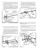
ASSEMBLY INSTRUCTIONS 3. Assemble the rear frame angle to the bottom and the two boom mount brackets to the top of the side angles as shown in figure 2. Use four 5/16" x 1" hex bolts and 5/16" nylock nuts. Do not tighten yet. TOOLS REQUIRED FOR ASSEMBLY (2) (2) (2) (1) (1) (1) (1) 7/16" Wrenches 1/2" Wrenches 9/16" Wrenches Adjustable Wrench Screwdriver Pliers Grease Gun 5/16" x 1" HEX BOLT BOOM MOUNT BRACKET REAR FRAME ANGLE 1.
. Assemble the axle through the side angles and the tongue. Fasten the axle to the side angles using two 1/4" x 2" hex bolts and two 1/4" nylock nuts. Do not tighten yet. See figure 4. 8. Assemble the hitch bracket down through the slot in the tongue and fasten it to the tongue using a 3/8" x 1" hex bolt and a 3/8" nylock nut. Tighten. See figure 6. 9. Assemble the hitch pin and 1/8" hairpin cotter to the hitch bracket and tongue. See figure 6.
IMPORTANT: Do not overtighten bolts fastening to tank. Tighten until lock washers are snug and flattened. 14. Assemble the (RH) and (LH) boom mount assemblies to the boom mount brackets using two 5/16" x 3/4" hex bolts and 5/16" nylock nuts. Fasten through the slotted hole in each boom mount assembly. Do not tighten yet. See figure 9. 15. Align the holes in the boom transport bracket with the holes in the ends of the boom mount assemblies as shown in figure 9.
24. Tie the hoses to the front of the boom using four nylon ties per side as shown in the front view in figure 13. After tightening, cut excess length off ends of ties . 25. Insert a 3/32" hair cotter pin into the welded pin at each end of the boom. These pins will be used to lock the boom arm to the transport bracket when the arm is in the folded position. See figure 13. 19.
IMPORTANT: Connect sprayer to 12 volt batteries only! 29. Connect the boom connecting hose and the return (bypass) hose to the "Y" valve fitting, placing a hose gasket in the swivel nut on each hose. Insert the return hose into the top of tank. See figure 15. BOOM CONNECTING HOSE 30. Hook up the wiring to the vehicle battery. Connect the red wire on the fused wire harness to the positive post on the battery or the "HOT" connection on a vehicle switch or the ammeter.
OPERATION ADJUSTING SPRAY GUN NOZZLE Turn the nozzle on the spray gun to adjust the spray from a cone shaped fine mist to a straight stream. The spray gun operating pressure should be controlled using the bypass valve on the "Y" fitting. Maximum spray gun pressure can be attained when the boom is shut off. BEFORE STARTING It is important to test the boom and spray gun with plain water first to check the sprayer for leaks and to set the spray pattern and nozzle pressure.
4. Set the desired boom pressure, spraying with plain water while making pressure adjustments. For best results stay in the 20 to 30 PSI range. (At 10 PSI the spray pattern begins to break up, and at 40 PSI some drift develops.) Refer to the tip chart on page 11. 5. Determine the appropriate speed at which to travel, based on the chosen pressure setting and the recommended application rate. Use the tip chart on page 11. MAINTENANCE 6.
U.S. GALLON TIP CHART Tip No. Spray Width Inches #3 80"-160" Tip No. Spray Width Inches #3 80"-160" Pressure PSI 10 20 30 Pressure PSI 10 20 30 Tip Capacity US Gallons Per Minute .30 .42 .52 Tip Capacity US Gallons Per Minute .30 .42 .52 1 MPH 44.2 63 76.8 GALLONS PER ACRE (BASED ON WATER) Not affected by spray width 2 MPH 3 MPH 4 MPH 5 MPH 7.5 MPH 22.1 14.8 11.1 8.9 5.9 31.5 20.9 15.7 12.6 8.4 38.4 25.8 19.3 15.4 10.3 1 MPH 1.0 1.4 1.8 GALLONS PER 1000 SQ. FT.
REPAIR PARTS FOR 45 GALLON SPRAYER MODEL 45-03252 69 59 12 80 21 80 20 19 18 15 21 20 19 80 23 24 25 23 77 81 90 42 40 41 43 A B 73 23 28 26 83 39 32 31 33 79 73 25 23 60 23 23 27 26 30 30 44 31 29 89 82 71 74 73 73 C 80 16 75 13 22 23 23 60 14 76 70 75 74 50 51 33 48 36 33 49 49 2 33 35 58 34 47 B 52 A 52 1 45 C 11 59 6 4 62 61 60 66 65 64 60 65 64 9 63 65 66 3 5 88 31 56 81 57 54 55 53 11 4 38 37 84 61 84 85 87 65 6 86 74 61
REPAIR PARTS FOR 45 GALLON SPRAYER MODEL 45-03252 REF. NO. PART NO.
NOTES 14
NOTES
the fastest way to purchase parts www.speedepart.com © 2004 Agri-Fab, Inc. REPAIR PARTS Agri-Fab, Inc. 303 West Raymond Sullivan, IL. 61951 217-728-8388 www.agri-fab.