Agri-Fab ® OWNERS MANUAL Model No. 45-0325 45 GALLON ATV SPRAYER CAUTION: Read Rules for Safe Operation and Instructions Carefully • • • • Assembly Operation Maintenance Repair Parts SpeedEPart the ra,,e,, wa_ topurch_,_ partswww.speedepart.com PRINTED IN USA FORM NO.
RULES FOR SAFE OPERATION Any power equipment can cause injury if operated improperly the equipment. Exercise caution at all times when operating or if the user does not understand equipment. how to operate 1. 2. 3. 4. 5. 6. 7. 8. 9. Read this owners manual carefully before attempting to assemble or operate this sprayer. Read your vehicle owners manual for operating and safety rules before using this equipment.
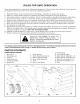
FULL SIZE HARDWARE CHART J H jl L U j KEY QTY. DESCRIPTION A B C D E F G H I J K L M 2 2 8 1 2 6 10 2 1 2 4 2 16 Hex Bolt, 3/8" x 4" Hex Bolt, 3/8" x 2-1/2" Hex Bolt, 3/8" x 1-1/4" Hex Bolt, 3/8" x 1" Hex Bolt, 3/8" x 3/4" Hex Bolt, 5/16" x 1" Hex Bolt, 5/16" x 3/4" Hex Bolt, 1/4" x 2" Carriage Bolt, 5/16" x 1-3/4" Screw, #10-24 x 1/2" Carriage Bolt, 3/8" x 1" Hex Lock Nut, 1/4" Hex Nut, 5/16" KEY QTY. N O P Q R S T U V W X Y Z 15 2 4 12 2 16 17 2 2 1 1 1 1 AA DESCRIPTION KEY QTY.
ASSEMBLY INSTRUCTIONS , Assemble the rear frame angle to the bottom and the two boom mount brackets to the top of the side angles as shown in figure 2. Use four 5/16" x 1" hex bolts, 5/16" lock washers and 5/16" hex nuts. Do not tighten yet.
. Assemble the axle through the side angles and the tongue. Fasten the axle to the side angles using two 1/4" x 2" hex bolts and two 1/4" hex lock nuts. Do not tighten 8. Assemble the hitch bracket down through the slot in the tongue and fasten it to the tongue using a 3/8" x 1" hex bolt, a 3/8" lock washer and a 3/8" hex nut. Tighten. See figure 6. Assemble the hitch pin and 1/8" hairpin cotter to the hitch bracket and tongue. See figure 6. yet. See figure 4. 9.
IMPORTANT:Do not overtighten bolts fasteningto tank.Tightenuntillockwashersaresnugandflattened. 11. Attachthe tanktothe frameusingsix 1/2"spacers withsix 3/8"x 1-1/4"hex bolts,3/8" lockwashers and3/8"flat washers.Placethe spacersbetween the tankandthe frame.Tighten the six boltsuntil the lockwashersare flattened.Seefigure8. 12. Assemblethe hosehooksto the front of the tank using two #10-24 x 1/2" screws, two 3/16" lock washersand two flanged spacers.Tighten the screwsuntil the lock washersare flattened.
19. Attachthe (RH) boomarm assemblyto the (RH) boom mount assemblyas shown in figure 11, usinga 3/8"x 4" hex bolt,three 3/8"flat washers, andone 3/8" hex lock nut. Do not overtighten. 20. Place a 3/8" x 2-1/2" hex bolt throughthe loose endofthe springandthenassemblea3/8" hexnut onto the bolt. Fasten the hex bolt to the boom mountassemblyusinga 3/8"lock washerand 3/8" hex nut. Tighten the nuts, exposingone or two threadson the end of the bolt. Seefigure 11. 21.
29. Connecttheboomconnectinghoseandthe return (bypass)hose to the "Y" valve fitting, placinga hosegasketin theswivel nuton eachhose.Insert the returnhoseintothe top of tank.Seefigure15. HOSE IM PO RTANT: 31. Hook up the red positive tion on GASKET Connect sprayer to 12 volt batteries only! the wiring to the vehicle battery. Connect wire on the fused wire harness to the post on the battery or the "HOT" conneca vehicle switch or the ammeter.
ADJUSTING OPERATION BEFORE STARTING It is important to test the boom and spray gun with plain water first to check the sprayer for leaks and to set the spray pattern and nozzle pressure. If a leak should occur, thread tape may be used to better seal the fitting. PUMP PRESSURE OPERATING ADJUSTMENT OF BOOM NOZZLES The boom valve on the "Y" fitting controls the flow to all the boom nozzles. It should be either completely open or completely closed.
4. Set the desired boom pressure,spraying with plain water while makingpressureadjustments. Forbestresultsstayin the 20 to30 PSIrange.(At 10 PStthe spray patternbeginsto breakup, and at 40 PSI somedrift develops.)Refer to the tip chart on page 11. 5. Determinetheappropriatespeedatwhichtotravel, based on the chosen pressure setting and the recommendedapplicationrate. Usethe tip chart on page 11. . 7. . 9. MAINTENANCE 1 . 2. Do not store sprayer with any solution left in tank.
U.S. GALLON Tip Spray No. Width Inches #3 80"-160" Tip Spray No. Width Inches #3 80"-160" Pressure PSt Tip Capacity US Gallons Per Minute .30 .42 .52 Pressure PSt Tip Capacity US Gallons Per Minute 1 MPH .30 .42 .52 1.0 1.4 1.8 10 20 3O 44.2 63 76.8 IMPERIAL Jet Size Spray Width Inches Pressure PSI (Bar) (mm) 10 #3 80"- 1 60" (2032 mm) (4064 mm) Jet Size Spray Width Inches (mm) (0.7) 20 (1.4) 30 (2.1) Pressure PSI (Bar) 10 #3 80"- 1 60" (2032 mm) (4064 mm) (0.7) 20 (1.4) 30 (2.
REPAIR PARTS FOR 45 GALLON MODEL SPRAYER 45-0325 21 / 20 ..19 8O 21 80 15 80 \ i _-19 23 18 \ 23 , 24 83 31 i29 J; 44 _.
REPAIR REF. NO. PART NO. QTY.
NOTES 14
NOTES 15
$#eedEPmrt_ _ _ to_ REPAIR PARTS Agri-Fab, Inc. 303 West Raymond Sullivan, IL. 61951 217-728-8388 www.agri-fab.com _ www.speedepart.