Agri-Fab ® OWNERS MANUAL Model No. 45-03072 45-03611 CAUTION: Read Rules for Safe Operation and Instructions Carefully _/,/_'_'u_'rdr/ PRINTED IN U.S.A. 42" ROUGH CUT TRAILMOWER • Safety • Assembly • Operation • Maintenance • Parts the fastest way to purchase parts www.speedepart.com FORM NO.
TABLE OF CONTENTS SAFETY RULES ...................................................... SAFETY AND OPERATIONAL HARDWARE ASSEMBLY DECALS ................ 5,6 CHART .................................................. ............................................................ OPERATION ......................................................... CUSTOMER RESPONSIBILITIES REPAIR PARTS ................................................... DIAGRAM ...................................................
SAFETY RULES Safe Operation Practices for Tow Behind Mowers IMPORTANT: THIS CUTTING MACHINE IS CAPABLE OF AMPUTATING HANDS AND FEET AND THROWING OBJECTS. FAILURE TO OBSERVE THE FOLLOWING SAFETY INSTRUCTIONS COULD RESULT IN SERIOUS INJURY OR DEATH. Im • • • • • • • • • • • • • • GENERAL OPERATION II. Read, understand, and follow all instructions in the manual and on the machine before starting. Read this operator's manual carefully.
IV. SERVICE Look for this symbol to point out important safety precautions. It means CAUTIONlll BECOME ALERTlll YOUR SAFETY IS INVOLVED. Use extra care in handling gasoline and other fuels. They are flammable and vapors are explosive, Use only an approved container. -Never remove gas cap or add fuel with the engine running. Allow engine to cool before refueling. Do not smoke. Never refuel the machine indoors.
SAFETY AND OPERATIONAL DECALS Replace decal immediately if damaged. Order by part number. See back cover. IE°'"='" ! KEEPHANDSandFEETAWAY ROTATING BLADES AND BELTS. KEEP ALL SHIELDS IN PLACE. KEEP HANDS AND FEET FROM UNDER MOWER.
SAFETY AND OPERATIONAL DECALS Replace decal immediately if damaged. Order by part number. See back cover.
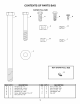
CONTENTS OF PARTS BAG SHOWN r FULL SIZE E 3 f J B NOT SHOWN FULL SIZE I I J I I I I I f I I I I J I REF. A B C D E F QTY. 1 2 2 1 3 1 DESCRIPTION Hex Bolt, 1/2" x 7" Hex Bolt, 3/8" x 2-3/4" Hex Bolt, 5/16" x 3/4" Hex Bolt, 1/4" x 3/4" Screw, Self Tapping #10 x 1/2" Hex Lock Nut, 1/2" REF. G H I J K 7 QTY.
ASSEMBLY TOOLS (1) (2) (2) (2) (2) REQUIRED FOR ASSEMBLY INSTALL 5/16" Wrench 7/16" Wrenches 1/2" Wrenches 9/16" Wrenches 3/4" Wrenches or Adjustable Wrenches • • • UNPACKING • Enclosed in packing crate are four items: 1. Mower Deck 2. Tow Bar Hitch Assembly 3. Box of Parts consisting of: • Rear Roller • Rear Roller Bracket • OIL Place Clutch Cable on top of Towbar Tube and align Cable Clips with bolt holes in Towbar Tube. Secure with three #10 Screws.
ASSEMBLY ENGINE MAGNETO GROUND (P_D WIRE) ENGINE GROUND BASE FEED WIRE HARNESS [] THROUGH THIS HOLE FRONT DRIVE COVER REAR QUADRANT 3/8 X 2-3/4 HEX BOLT CLUTCH LEVER 3/8 FLAT WASH E R #10 SCREW (3) / / CLUTCH / / CABLe// = / / CABLE CLIPS (3) TOW BAR TUBE 3/8 HEX LOCK NUT CABLE GUIDE 3/8 FLAT WASHER 1/4 X 3/4 HEX BOL_ \ H,TCH ASSEM L .. i CLUTCH CABLE 5/16 HEX NUT (2) MOUNTING ANCHOR FIG.
ASSEMBLY INNER NUT CLUTCH CABLE ADJUSTMENT / / • • • / / Remove four screws from Rear Drive Cover. Lay aside cover and screws. / / / OUTER NUT Place Clutch Lever in "DISENGAGED" position The Cable should be under slight tension but should not pull the Clutch Lever more than 1/8" away from the Switch Body. NOTE: If the Plunger extends more than 1/8" out from the switch body, the cable tension is too tight and the Engine will not start.
ASSEMBLY INSTALL • • • REAR ROLLER TO DECK Install Rear Roller Mounting Bracket to rear of deck using two 5/16 x 3/4 Hex Bolts and two 5/16 Hex Lock Nuts. (See Fig. 3.) Install Roller to Rear Roller Bracket using 1/2 x 7 Hex Bolt and 1/2 Hex Lock Nut. Make sure Roller turns freely on Bolt. 5/16 X 3/4 HEX BOLTSB AND 5/16 HEX LOCK NUTS "h ROLLER 1/2 X 7 HEX BOLT REAR ROLLERB MOUNTING BRACKET 1/2 HEX LOCK NUT FIG.
OPERATION KNOW YOUR MOWER READ THIS OWNER'S MANUAL AND SAFETY RULES BEFORE OPERATING YOUR MOWER. Compare the illustrations with your mower to familiarize yourself with the location of various controls and adjustments. Save the manual for future reference. EN FULL __THROTTLE RECOIL START HANDLE HEIGHT ADJUSTMENT STRAP MOWER BLADEE] CLUTCH LEVER SHUT OFFE] CONTROL TOW HITCH OFFSETE] ADJUSTMENT TOW BAR HEtGHTE] ADJUSTMENT FIG.
OPERATION The operation of any mower can result in foreign objects being thrown into the eyes, which can result in severe eye damage. Always wear safety glasses or eye shields before starting your mower and while mowing. We recommend wide vision safety mask for over the spectacles or standard safety glasses. CHILDREN Tragic accidents can occur if the operator is not alert to the presence of children. Children are often attracted to the machine and the mowing activity.
OPERATION MOWER HEIGHT ADJUSTMENT FRONT CAUTION: SHUT OFF MOWER ENGINE AND REMOVE _ To obtain the best cutting results, the mower housing should be adjusted so that the front is approximately 1/4" to 3/4" lower than the rear. To check front to back adjustment measure from the bottom edge of the deck to the ground at both front and rear of the deck.
OPERATION TOW HITCH OFFSET ADJUSTMENT CAUTION: SHUT OFF MOWER ENGINE AND REMOVE This mower has been designed to run offset from the center of the tow vehicle. This allows the operator to drive along side high brush with the tow vehicle while cutting down the brush beside him. The adjustable hitch gives you three offset cutting positions plus straight behind for narrow paths.
OPERATION BEFORE STARTING ENGINE MOWING Fill engine with oil. (See engine manual for proper orocedure and requirements) Add gasoline. Fill fuel tank using fresh clean unleaded gasoline. (See engine manual for safe filling procedure and storage instructions) I t CAUTION: TRAGIC ACCIDENTS CAN OCCUR IF THE OPERATOR IS NOT ALERT TO THE PRESENCE OF CHILDREN. CHILDREN ARE OFTEN ATTRACTED TO THE MACHINE AND THE MOWING ACTIVITY. NEVER ASSUME THAT CHILDREN WILL REMAIN WHERE YOU LAST SAW THEM.
CUSTOMER GENERAL RESPONSIBILITIES RECOMMENDATIONS Once a year you should replace the spark plug, clean or replace air filter, and check blades and belts for wear. A new spark plug and clean air filter assure proper air-fuel mixture and help your engine run better and last longer. The warranty on this Vehicle does not cover items that have been subjected to operator abuse or negligence. To receive full value from the warranty, operator must maintain unit as instructed in this manual.
CUSTOMER BLADE RESPONSIBILITIES CARE AND SERVICE BLADE ASSEMBLY CAUTION: BARE HANDS. CARELESS OR IMPROPER DO NOT HANDLE MOWER BLADES WITH HANDLING MAY RESULT IN SERIOUS INJURY. BLADE CARE For best results mower blades must be kept sharp. The blades can be sharpened with a file or on a grinding wheel. Do not attempt to sharpen blades while they are still on the mower. BLADE SERVICE (Refer to fig. 9) TO • • • REMOVE BLADE ASSEMBLY FROM DECK Remove cotter pin from the spindle shaft.
CUSTOM R RESPONSIBILITIES INNER NUT / CLUTCH CABLE ADJUSTMENT J • \ \\ , OUTER NUT / Remove four screws from Rear Drive Cover. Lay aside cover and screws. • Place Clutch Lever in "DISENGAGED" position • The Cable should be under slight tension but should not pull the Clutch Lever more than 1/8" away from the Switch Body. NOTE: If the Plunger extends more than 1/8" out from the switch body, the cable tension is too tight and the Engine will not start.
CUSTOMER RESPONSIBILITIES INSTALLING NEW V-BELT V-BELT REPLACEMENT • • V-belt must be replaced if it becomes stretched to the point that it can no longer be adjusted, or if it becomes frayed or otherwise can not function properly. Move Blade Clutch Lever to the "DISENGAGED" position. • • • • I,_ DISCONNECT CAUTION: SPARK PLUG WIRE • • REMOVING OLD V-BELT • Remove Rear Drive Cover. • Remove Front Drive Cover. • Remove Hair Pin and Clevis Pin from Clutch Cable.
STORAGE Immediately prepare your mower for storage at the end of the season or if the unit will not be used for 30 days or more. ENGINE OIL Drain oil (with engine warm) and replace with clean engine oil. (See engine manual) MOWER CYLINDER When the mower is to be stored for a period of time, clean it thoroughly, remove all dirt, grease, leaves, etc. Store in a clean dry area. • Clean entire mower (See =CLEANING") • Lubricate as shown in the Customer Responsibilities section of this manual.
42" ROUGH CUT TRAILMOWER - MODELS 45-03072 & 45-03611 @ @ 22
42" ROUGH CUT TRAILMOWER - MODELS 45-03072 & 45-03611 ITEM PART NO. DESCRIPTION ITEM PART NO. 1. HA24255 MOWER DECK 41. HA24312 ROD CHAIN 2. HA24378 GUARD WHEEL 42. HA24313 BRACKET CHANNEL 3. HA23193 SCREW 3/8-16 X 1-1/4 THD. FORMING 43. HA9131 SCREW SELF THREADING 4. HA24292 BRACKET 44. 25428 PLATE ENGINE MOUNTING 5. HA24293 ROD BELT GUIDE 45. 49161* ENGINE, 11 HP 6. HA3090 PIN HAIR COTTER 46. HA24457 PULLEY 7. HA24294 V-BELT (B SEC. 60" O.C.) 47.
42" ROUGH CUT TRAILMOWER - MODELS 45-03072 24 & 45-03611
42" ROUGH CUT TRAILMOWER - MODELS 45-03072 ITEM PART NO. DESCRIPTION 1. 64906 IDLER MOUNTING 2. 64899 IDLER ARM 3. 24472 BUSHING 4. 43070 WASHER FLAT 5. 43003 WASHER 3/8" LOCK 6. 43062 BOLT 3/8-16 X 1-1/2" HEX HEAD 7. 49148 SPACER 8. HA21341 IDLER PULLEY (FLAT) 9. 43054 BOLT 3/8-16 X 2" HEX HEAD 10. 43082 NUT 3/8-16 HEX LOCK 11. HA22981 GUIDE BELT 12. HA22224 SCREW 3/8-16 X 3/4 SELF TAPPING 13. 43087 BOLT 3/8-16 X 1-1/4" HEX HEAD 14. HA15200 WASHER FLAT 15.
42" ROUGH CUT TRAILMOWER - MODELS ITEM PART NO. DESCRIPTION 1. 25273 TUBE DRAWBAR HA24321 TUBE DRAWBAR 2. HA24441 STRAP HITCH 3. HA20186 SPRING EXTENSION 4. 44180 5. 43064 6. 7. 8. 45-03072 & 45-03611 ITEM PART NO. DESCRIPTION (MODEL 45-0361) 17. 43013 NUT 1/4-20 LOCK (MODEL 45-03071 ) 18. HA23262 DECAL ENGINE SHUT-OFF 19. HA23265 DECAL CLUTCH LEVER 20. 64910 BRACKET DRAWBAR ADJUSTMENT BOLT 5/16-18 X 2" HEX HEAD 21.
WIRING DIAGRAM SWITCH -- BLACK WIRE FROM MODULE TO ENGINE BLACK WIRE FROM ON/OF SWITCH TO MAGNETO GROUND \ ENGINE BLACK WIRE FROM ON/OFF SWITCH TO ENGINE GROUND 27 ELECTRONIC CONTROL MODULE
SpeedEPart_ _, _ __ _ REPAIR PARTS © 2004 Agri-Fab, Inc. Agri-Fab, Inc. 303 West Raymond Sullivan, IL. 61951 217-728-8388 www.agri-fab.com www.speedepart.