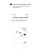
™ OWNERS MANUAL Model No. 45-03621 45-03622 42" ROUGH CUT TRAILMOWER CAUTION: Read Rules for Safe Operation and Instructions Carefully IMPORTANT: BATTERY REQUIRED!! The battery is NOT included with the deck but must be purchased separately. A 12 volt lawn tractor battery with 260/300 cold cranking amps and dimensions of 6-1/8"H x 7-5/8"L x 5-1/8"W is recommended to operate the machine. • • • • • Safety Assembly Operation Maintenance Parts the fastest way to purchase parts www.speedepart.
TABLE OF CONTENTS SAFETY RULES........................................................................................... 3,4 SAFETY AND OPERATIONAL DECALS..................................................... 5,6 HARDWARE CHART....................................................................................... 7 ASSEMBLY................................................................................................. 8-11 OPERATION...........................................................................
SAFETY RULES Safe Operation Practices for Tow Behind Mowers IMPORTANT: THIS CUTTING MACHINE IS CAPABLE OF AMPUTATING HANDS AND FEET AND THROWING OBJECTS. FAILURE TO OBSERVE THE FOLLOWING SAFETY INSTRUCTIONS COULD RESULT IN SERIOUS INJURY OR DEATH. I. GENERAL OPERATION II. SLOPE OPERATION • Slopes are a major factor related to loss-of-control and tip over accidents, which can result in severe injury or death. All slopes require extra caution. If you feel uneasy on it, do not mow it.
IV. SERVICE • • • • • • • • Look for this symbol to point out important safety precautions. It means CAUTION!! BECOME ALERT!! YOUR SAFETY IS INVOLVED Use extra care in handling gasoline and other fuels. They are flammable and vapors are explosive. -- Use only an approved container. -- Never remove gas cap or add fuel with the engine running. Allow engine to cool before refueling. Do not smoke. -- Never refuel the machine indoors.
CONTENTS OF PARTS BAG SHOWN FULL SIZE A B C D E F I G H J L K NOT SHOWN FULL SIZE M REF. QTY. DESCRIPTION A 1 Hex Bolt, 1/2" x 7" B 2 Hex Bolt, 1/4" x 7-1/2" C 2 Hex Bolt, 5/16" x 3/4" D 2 Hex Bolt, 1/4" x 3/4" E 2 Screw, Self Tapping #10 x 1/2" F 1 Hex Nylock Nut, 1/2" N REF. QTY.
ASSEMBLY INSTALL TOWBAR TUBE TO REAR QUADRANT • • • • Place Towbar Tube into Rear Quadrant, align holes and insert 3/8 x 2-3/4 Hex Bolt through quadrant and rear hole of Tube. Secure tightly with 3/8 Hex Lock Nut and then loosen 1/4 turn to allow Tube to pivot freely inside Rear Quadrant. Insert 3/8 X 2-3/4 Bolt and 3/8 Flat Washer into slot in Rear Quadrant and into hole in Towbar Tube.
ASSEMBLY TERMINAL ACCESS DOORS 1/4 X 3/4 HEX BOLT & 1/4 HEX NUT (SEMS) BATTERY COVER BLACK WIRE SCREW (4) + BATTERY HOLD DOWN 1/4 X 7-1/2 HEX BOLT PLASTIC NUT RED WIRE 1/4 X 7-1/2 HEX BOLT REAR QUADRANT 3/8 X 2-3/4 HEX BOLT CLUTCH LEVER 3/8 FLAT WASHER #10 SCREW (2) CABLE CLIP (2) 3/8 FLAT WASHER 3/8 HEX LOCK NUT 1/4 X 3/4 HEX BOLT HITCH ASSEMBLY CLUTCH CABLE 5/16 HEX NUT (2) FIG.
ASSEMBLY INNER NUT CLUTCH CABLE ADJUSTMENT • OUTER NUT Remove four screws from Rear Drive Cover. Lay aside cover and screws. • Place Clutch Lever in “DISENGAGED" position • The Cable should be under slight tension but should not pull the Clutch Lever more than 1/8" away from the Switch Body. NOTE: If the Plunger extends more than 1/8" out from the switch body, the cable tension is too tight and the Engine will not start.
ASSEMBLY INSTALL REAR ROLLER TO DECK • • • Install Rear Roller Mounting Bracket to rear of deck using two 5/16 x 3/4 Hex Bolts and two 5/16 Hex Nylock Nuts. (See Fig. 3.) Install Roller to Rear Roller Bracket using 1/2 x 7 Hex Bolt and 1/2 Hex Nylock Nut. Make sure Roller turns freely on Bolt. 5/16 X 3/4 HEX BOLTS AND 5/16 HEX LOCK NUTS ROLLER 1/2 X 7 HEX BOLT REAR ROLLER MOUNTING BRACKET 1/2 HEX LOCK NUT FIG.
OPERATION HEIGHT ADJUSTMENT STRAP MOWER BLADE CLUTCH LEVER IGNITION KEY SWITCH HEIGHT ADJUSTMENT LIFT LEVER TOW HITCH OFFSET ADJUSTMENT HEIGHT ADJUSTMENT STRAP TOW BAR HEIGHT ADJUSTMENT THROTTLE CONTROL FIG.
OPERATION 13
OPERATION 14
OPERATION HAIR COTTER PIN HAIR COTTER PIN HEIGHT ADJUSTMENT STRAP LOCATING PIN HEIGHT ADJUSTMENT LIFT LEVER CUTTING HEIGHTS CLEVIS PIN 1-1/2" 2" 2-1/2" 3" 3-1/2" 4" 4-1/2" 5" TOW BAR ADJUSTMENT TOW BAR CUTTING HEIGHT GROUND LEVEL FIG.
OPERATION This mower has been designed to run offset from the center of the tow vehicle. This allows the operator to drive along side high brush with the tow vehicle while cutting down the brush beside him. The adjustable hitch gives you three offset cutting positions plus straight behind for narrow paths. MODEL 45-0362 The adjustable hitch of this mower can be set in seven positions including straight and offsets of 9", 17" and 23" on both sides. (See Fig.
CUSTOMER RESPONSIBILITIES WHEEL PIVOT 3 SPINDLE 2 WHEEL 2 SWIVEL 2 QUADRANT 3 17 WHEEL 2 WHEEL PIVOT 3
CUSTOMER RESPONSIBILITIES BLADE CARE AND SERVICE BLADE ASSEMBLY TERMINAL AC CAUTION: DO NOT HANDLE MOWER BLADES WITH BARE HANDS. CARELESS OR IMPROPER HANDLING MAY RESULT IN SERIOUS INJURY. 1/4 X 3/4 HEX BOLT & 1/4 HEX NUT (SEMS) BLACK WIRE BLADE CARE For best results mower blades must be kept sharp. The blades can be sharpened with a file or on a grinding wheel. Do not attempt to sharpen blades while they are still on the mower. BATTERY HOLD DOWN BLADE SERVICE (Refer to fig.
CUSTOMER RESPONSIBILITIES INNER NUT CLUTCH CABLE ADJUSTMENT • OUTER NUT Remove four screws from Rear Drive Cover. Lay aside cover and screws. • Place Clutch Lever in “DISENGAGED" position • The Cable should be under slight tension but should not pull the Clutch Lever more than 1/8" away from the Switch Body. NOTE: If the Plunger extends more than 1/8" out from the switch body, the cable tension is too tight and the Engine will not start.
CUSTOMER RESPONSIBILITIES V-BELT REPLACEMENT • • INSTALLING NEW V-BELT V-belt must be replaced if it becomes stretched to the point that it can no longer be adjusted, or if it becomes frayed or otherwise can not function properly. Move Blade Clutch Lever to the “DISENGAGED" position. • • • • CAUTION: DISCONNECT SPARK PLUG WIRE • • REMOVING OLD V-BELT • Remove Rear Drive Cover. • Remove Front Drive Cover. • Remove Hair Pin and Clevis Pin from Clutch Cable.
STORAGE 21
42" ROUGH CUT TRAILMOWER - MODELS 45-03621 & 45-03622 22
42" ROUGH CUT TRAILMOWER - MODELS 45-03621 & 45-03622 ITEM PART NO. DESCRIPTION ITEM PART NO. DESCRIPTION 1. 2. 3. 4. 5. 6. 7. 8. 9. 10. 11. 12. 13. 14. 15. 16. 17. 18. 19. 20. 21. 22. 23. 24. 25. 26. 27. 28. 29. 30. 31. 32. 33. 34. 35. 36. 37. 38. 39. 40. 41. 42. 43. 44. 45. 46. 47. MOWER DECK GUARD WHEEL SCREW 3/8-16 X 1-1/4 THD. FORMING BRACKET BELT GUIDE ROD BELT GUIDE PIN HAIR COTTER V-BELT (B SEC. 60" O.C.
42" ROUGH CUT TRAILMOWER - MODELS 45-03621 & 45-03622 40 9 12 4 11 8 23 34 6 5 7 4 2 21 3 1 18 20 22 33 13 14 25 22 18 25 32 15 16 17 39 18 30 21 31 19 28 23 24 37 26 25 41 5 4 36 28 27 35 27 38 6 28 15 29 24 28
42" ROUGH CUT TRAILMOWER - MODELS 45-03621 & 45-03622 ITEM PART NO. DESCRIPTION 1. 2. 3. 4. 5. 6. 7. 8. 9. 10. 11. 12. 13. 14. 15. 16. 17. 18. 19. 20. 21. 22. 23. 24. 25. 26. 27. 28. 29. 30. 31. 32. 33. 34. 35. 36. 37. 38. 39. 40. 41. 42. 43.
42" ROUGH CUT TRAILMOWER - MODELS 45-03621 & 45-03622 ITEM PART NO. DESCRIPTION ITEM PART NO. DESCRIPTION 1. 2. 3. 4. 5. 6. 8. 9. 10. 11. 12. 13. 14. 15. 25273 HA24441 HA20186 44180 47810 64909 43509 1038 HA21362 HA23636 47134 49157 43062 HA19445 TUBE DRAWBAR (MODEL 45-0361) STRAP HITCH SPRING EXTENSION BOLT 5/16-18 X 2" HEX HEAD NUT, HEX 5/16-18 NYLOCK HITCH ASSEMBLY BOLT 3/8-16 X 2-3/4 HEX HEAD NUT 3/8 NYLOCK JAM NUT, HEX 3/8-16 NYLOCK PIN CLEVIS PIN HAIR COTTER .08 X 1.
BLACK WIRE GRAY WIRE BLUE WIRE RED WIRE STARTER 11 SWITCH 12 INTERLOCK SWITCH 10 WHITE WIRE 1 49193 48097 49196 49192 49244 HA23787 49197 HA237888 HA237544 HA231999 HA237494 2491545 43012 46978 1. 2. 3. 4. 5. 6. 7. 8. 9. 10. 11. 12. 13. 14. 5 PART NO.
the fastest way to purchase parts www.speedepart.com © 2004 Agri-Fab, Inc. REPAIR PARTS Agri-Fab, Inc. 809 South Hamilton Sullivan, IL. 61951 217-728-8388 www.agri-fab.