45-0543 32" POLY SPIKER/SPREADER ..................................................................4 ESPAÑOL..........................................................13 ENGLISH..........................................................6 FRANÇAIS.........................................................16 the fastest way to purchase parts www.speedepart.com FORM NO.
7 48 27 52 53 2 22 51 41 7 33 55 26 22 20 22 35 56 33 54 35 66 16 57 7 44 65 33 3 11 7 13 17 14 36 34 23 33 22 4 20 26 39 7 2 49 24 26 19 20 26 36 33 22 37 43 30 61 62 20 64 37 63 56 7 51 33 6 52 34 29 33 22 40 22 38 18 60 58 12 27 33 28 20 59 7 22 42 22 23 1 5 35 23 9 27 32 27 47 8 22 33 22 31 8 22 41 50 48 45 22 11 26 15 10 46 21 25 46 PARTS FOR 32" POLY SPIKER/SPREADER MODEL 45-0543
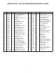
PARTS FOR 32" POLY SPIKER/SPREADER MODEL 45-0543 REF. PART NO. QTY. 1 2 3 4 5 6 7 8 9 10 11 12 13 14 15 16 17 18 19 20 21 22 23 24 25 26 27 28 29 30 31 32 33 34 47953 24743 24747 47931 28557 41863 28606 69416 28558 28556 28555 64106 45100 47025 43796 43224 44180 44215 1509-90 46524 47623 741-0249 43093 44101 43343 47189 47810 48115 43019 43012 44731 43182 R19212016 R19171616 1 1 1 1 1 2 7 2 1 1 2 1 2 2 2 4 1 1 1 5 1 13 3 1 1 7 10 2 2 1 2 1 9 4 DESCRIPTION REF. PART NO. QTY.
RULES FOR SAFE OPERATIONS Any power equipment can cause injury if operated improperly or if the user does not understand how to operate the equipment. Exercise caution at all times, when using power equipment. • • • • • • • Read this owner's manual before attempting to assemble or operate the spiker/spreader. Read the towing vehicle owner's manual and know how to operate the tractor before using the spiker/spreader attachment. Do not allow anyone to ride on or sit on the spiker/ spreader.
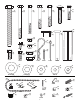
15 (2) 14 (2) 13 (2) 17 (1) 16 (4) 19 (1) 18 (1) 1509-90 44215 44180 43224 20 (5) 22 (13) 43796 741-0249 26 (7) 47025 25 (1) 47189 27 (10) 31 (2) 45100 32 (1) 30 (1) 43182 43012 24 (1) 28 (2) 48115 29 (2) 43343 43019 33 (9) 44101 34 (4) R19212016 47 (1) 23 (3) 47810 44731 21 (1) 43093 35 (6) 46524 36 (2) 37 (2) 43088 1543-69 43081 R19171616 47623 NOT SHOWN FULL SIZE 45 (1) 46 (2) 24446 48 (2) 49449 44 (1) 47777 43848 43943 42 (2) 47959 47969 41 (2) 50 (
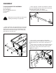
ASSEMBLY TOOLS REQUIRED FOR ASSEMBLY • On the right side, assemble the handle brace bracket (5) to the lift handle (9) using a 5/16" x 3/4" hex bolt (32) and 5/16" nylock nut (27). See figure 2. • Assemble the grip (45) onto the lift handle. (2) 7/16" Wrenches (2) 1/2" Wrenches (2) 3/4" or Adjustable Wrenches (1) Screwdriver (1) Pliers 32 5 Spike points are sharp. Exercise caution when handling and working near spike disks.
• On the left side, insert a 5/16" x 3-1/2" hex bolt (14) through the upper hole on the transport tube (10), a spacer (42), and the hitch tube. Secure with a 5/16 nylock nut (27). Do not tighten yet. See figure 4. • Assemble a 1/2" x 4" hex bolt (13), a .531 washer (34), a wheel (6), a .531 washer (34), and a .5" jam nut (29). Finger tighten only. • Attach the wheel assembly to the transport tube using a 1/2" nylock jam nut (28). Repeat for the other side. See figure 6.
• Screw a 1/4" nylock hex nut (26) all the way onto the flow control link (44). Assemble the ferrule (49) onto the link and then start a 1/4" nylock hex nut one or two turns onto the link. See figure 7. • Assemble the ferrule (49) into the hole at the end of the flow control lever (2) using a 1/4" nylock hex nut (26). Tighten the nut, leaving it loose enough that the ferrule can pivot. See figure 7. • Assemble the grip (43) onto the end of the flow control lever. See figure 7.
• Move the flow control lever (2) as far as it will go to the "OFF" position. Push the feed plate back as far as it will go to the closed position. See figure 10. • Place a nylon washer (36) onto the bent end of the flow control link (44) and then insert the link into the feed plate bracket. Secure it with a 3/32" x 3/4" cotter pin (24). See figure 10.
• Place a short spacer tube (41), a drive disk (8), a 5/8" flat washer (33), another drive disk and a second 5/8" flat washer onto the shaft. Fit the short spacer tube onto the flanged bearing in the end plate. See figure 14. • Place a 5/8" flat washer (33), the compression spring (38) and another 5/8" flat washer onto the shaft. See figure 16. 33 8 41 38 33 FIGURE 16 FIGURE 14 • Place two spike disks (7), separated by a long spacer tube (20), onto the shaft.
• Place two spike disks (7), separated by a long spacer tube (20), onto the shaft. Fit the long spacer tube onto the ends of the flanged bearings in the disks. See figure 19. • Place one or two 5/8" flat washers (33) onto the end of the spike disk shaft and secure the shaft with a 1/8" x 1-1/2" cotter pin (23) by spreading the ends of the cotter pin. See figure 22. • Fasten the two drive disks to the shaft using two 1/8" x 1-1/2" cotter pins (23) by spreading the ends of the cotter pin. See figure 22.
OPERATION SETTING CHART MATERIAL HOW TO USE YOUR SPIKER/SPREADER 1. Refer to the instruction label on the material package and to the instruction decal on your spreader to help determine the proper spreader setting and application rate. Also see the Setting Chart on this page for a general range of settings for commonly used materials. 2. Determine the approximate square footage of the area to be covered and estimate the amount of fertilizer or seed required. 3.
ESPAÑOL REGLAS PARA UNA OPERACIÓN SEGURA Cualquier equipo motriz puede causar lesiones si no se opera correctamente o si el usuario no entiende la forma de operar el equipo. Tenga siempre cuidado cuando use un equipo motriz. • • • • • • Lea este manual de instrucciones con mucho cuidado antes de tratar de armar u operar este surcador-esparcidor. Lea el manual de instrucciones del tractor y conozca bien la forma de operar el tractor antes de usar este equipo surcadoresparcidor.
• • • • Coloque el anclaje central (3) en la tolva. Inserte un perno hexagonal de 1/4" x 1-1/4" (19) por el anclaje central y la parte frontal de la tolva. Colo-que una arandela plana de 1/4" (37), la palanca de control de flujo y una tuerca hexagonal de seguridad de nylon de 1/4" (26) en el perno. No apriete todavía. Consulte la figura 8. Inserte un perno hexagonal de 1/4" x 3/4" (30) por el anclaje central y la parte posterior de la tolva.
ESPAÑOL OPERACIÓN CUADRO DE AJUSTE FORMA DE USAR ESPARCIDOR SU EQUIPO MATERIAL SURCADOR- 1. Lea la etiqueta de instrucciones en el paquete de materiales y la calcomanía de instrucciones en el esparcidor para determinar el ajuste apropiado del esparcidor y la velocidad de aplicación. También vea, en el Cuadro de Ajuste de esta página, una gama general de los ajustes posibles para los materiales usados con mayor frecuencia. 2.
FRANÇAIS RÈGLES DE SÉCURITÉ D’UTILISATION Tout équipement à moteur peut causer des blessures s’il est mal utilisé ou si l’utilisateur ne sait pas comment l’utiliser. Il faut faire attention en permanence pour utiliser l’équipement à moteur. • • • • • • • Lire ce manuel du propriétaire avant d’essayer d’assembler ou d’utiliser la cramponneuse/répandeuse.
• • • • • • • • • • • Assembler l’embout (43) sur l’extrémité du levier de commande de débit. Voir figure 7. Placer le levier de commande dans la fente de la trémie. Voir figure 8. Placer le renfort central (3) dans la trémie. Insérer un boulon à tête hexagonale de 1/4 po x 1 1/4 po (19) dans le renfort central et le devant de la tré-mie. Assembler une rondelle plate de 1/4 po (37), le levier de commande de débit et un écrou nylock hexagonal de 1/4 po (26) sur le boulon. Ne pas encore serrer.
FRANÇAIS FONCTIONNEMENT TABLEAU DE RÉGLAGE COMMENT UTILISER RÉPANDEUSE LA MATÉRIAU TYPE CRAMPONNEUSE/ Fertilisant 1. Se reporter à l’étiquette d’instructions sur l’emballage du matériau et à l’autocollant d’instructions sur la répandeuse pour aider à déterminer le réglage et le taux d’application appropriés de la répandeuse. En outre, voir le Tableau de réglage sur cette page pour une plage de réglages générique correspondant aux matériaux les plus fréquemment utilisés. 2.
NOTES 19
the fastest way to purchase parts www.speedepart.com REPAIR PARTS Agri-Fab, Inc. 303 West Raymond Sullivan, IL. 61951 217-728-8388 www.agri-fab.