OWNER'S MANUAL MODEL NO. 45-05191 Utility 17 Poly Cart CAUTION: Read Rules for Safe Operation and Instructions Carefully • • • • • Safety Assembly Operation Maintenance Repair Parts the fastest way to purchase parts www.speedepart.com Printed in U.S.A. FORM NO. 41821 rev.
SAFETY Remember, any power equipment can cause injury if operated improperly or if the user does not understand how to operate the equipment. Exercise caution at all times when using power equipment. CAUTION: VEHICLE BRAKING AND STABILITY MAY BE AFFECTED WITH THE ADDITION OF AN ACCESSORY OR AN ATTACHMENT. BE AWARE OF CHANGING CONDITIONS ON SLOPES. LOOK FOR THIS SYMBOL TO POINT OUT IMPORTANT SAFETY PRECAUTIONS. IT MEANS – ATTENTION! BECOME ALERT! YOUR SAFETY IS INVOLVED.
FULL SIZE HARDWARE CHART SHOWN FULL SIZE E B A D C F G J H I NOT SHOWN FULL SIZE L N M K REF QTY. DESCRIPTION REF QTY.
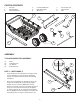
CARTON CONTENTS 1. 2. 3. Poly Tray Wheel Support Latch Stand Plate 4. 5. 6. Latch Stand Bracket Draw Bar Tongue Wheels (2) 7. 8. 9. Foot Pedal Latch Hitch Bracket Axle 1 3 2 4 7 9 8 5 6 ASSEMBLY TOOLS REQUIRED FOR ASSEMBLY (1) (2) (2) (2) Pliers 7/16" Wrenches 1/2" Wrench 9/16" Wrenches G step 1: (see figure 1) • Verify that all parts and all fasteners on pages 3 and 4 are included in the carton and parts bag. Refer to page 3 to identify fasteners used in the following instructions.
step 2: (see figure 2) • step 4: (see figure 4) Hook the short end of the spring (M) into the hole in the foot pedal latch. Use the spring puller tool (L) to hook the long end of the spring into the square hole in the tongue. The spring puller tool can be stored when finished. • Lay the tongue (open side facing up) onto the wheel support (2). Assemble the axle (9) through the wheel support and the tongue.
step 6: (see figure 6) • step 7: (see figure 7) Assemble the latch stand plate (3) and the latch stand bracket (4) at the front of the tray using four hex bolts (C), and hex nuts (E). The aligning tab on the bottom of the latch stand bracket must be towards the rear of the cart. Tighten. • Place the tray onto the wheel support and position it so that the latch stand bracket locks into the foot pedal latch. Fasten the tray to the wheel support using eight hex bolts (D) and hex nuts (F). Tighten.
NOTES 7
OPERATION MAINTENANCE 1. CAUTION: VEHICLE BRAKING AND STABILITY MAY BE AFFECTED WITH THE ADDITION OF AN ACCESSORY OR AN ATTACHMENT. BE AWARE OF CHANGING CONDITIONS ON SLOPES. 1. At the beginning of each season, using a light machine oil, lubricate the latch, the latch pivot bolt, and the area of the axle where the draw bar tongue pivots. 2. Grease or oil the wheel bearings periodically. Use automotive wheel bearing type grease or 20 weight oil.
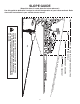
(Keep this sheet in a safe place for future reference.) Use this guide to determine if a slope is safe for the operation of your tractor and cart. Refer also to the instructions in your vehicle owners manual. SLOPE GUIDE SIGHT AND HOLD THIS LEVEL WITH A VERTICAL TREE A POWER POLE A CORNER OF A BUILDING OR A FENCE POST F O L D A LONG DOTTE D L IN E , REPR ESENT ING A 1 0 DEGRE E SLO PE CAUTION: DO NOT OPERATE YOUR TRACTOR AND CART ON A SLOPE IN EXCESS OF 10 DEGREES.
REPAIR PARTS ILLUSTRATION MODEL NUMBER 45-05191 1 18 20 3 4 19 2 15 6 13 7 15 17 24 22 11 9 14 13 8 16 16 5 23 21 12 10 10
REPAIR PARTS LIST MODEL NUMBER 45-05191 REF. PART NO. QTY.
the fastest way to purchase parts www.speedepart.com REPAIR PARTS Agri-Fab, Inc. 809 South Hamilton Sullivan, IL. 61951 217-728-8388 www.agri-fab.