
User's Manual


18/12/13 Page 5 of 8
ABR200 Antenna Tuning Manual
The following picture shows how additional capacitors have to be connected to the ABR200:
In this example there are 3 additional capacitors, which can be set with jumpers. On a
customer’s PCB one capacitor (or maybe 2) with the correct value would be enough BUT the
correct value is not the same for every unit. The antenna tuning has to be done for every reader
individually! Change the capacitance until you have reached the maximum antenna voltage.
2 Tuning the antenna using ASR-PC-Demo
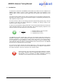
Start ASR-PC-Demo and connect the ABR200 to the software. Go to the “Tuning” tab.
The antenna voltage can be requested from the
ABR200 by pressing the “get” button. The
voltage depends on the antenna Q (inductance
and resistance). In this example the antenna Q
is pretty high (>>100) and thus the antenna
voltage is also fairly high (but absolutely ok).
In order to request the antenna voltage
repeatedly you can check the box “poll”. The
PC-Software will request the readers antenna
voltage until the box is unchecked again. This
can be useful while moving the coil on a ferrite
rod in order to tune to the correct inductance.
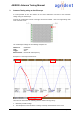
In this example the voltage of the antenna is 305V. This value could differ from the antenna
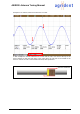
voltage measured with an oscilloscope. Change the coil position on the antenna rod until the
maximum voltage is reached. Try to find the maximum very carefully since small changes of the
coil position result in big changes of the antenna voltage.