Agrident GmbH, Steinklippenstr. 10, D-30890 Barsinghausen Phone +49 5105 582573-10 - Fax +49 5105 582573-17 APR650 User Manual Firmware v1.
APR650 User Manual © Copyright 2020 by Agrident GmbH TB All rights reserved. No part of this publication may be reproduced, stored in a retrieval system, or transmitted, in any form or by any means, electronic, mechanical, photocopying, recording or otherwise, without prior written permission of Agrident GmbH. Agrident GmbH reserves the right to make changes to any and all parts of this documentation without obligation to notify any person or entity of such changes.
APR650 User Manual Content 1 Introduction.......................................................................................................... 5 2 Before you start ................................................................................................... 5 3 Reader Hardware ................................................................................................ 6 4 3.1 Parts of the APR650..................................................................................... 6 3.
APR650 User Manual 8.5.4 Print Barcode ...................................................................................... 33 8.5.5 Setup Printer ....................................................................................... 33 8.5.5.1 Set Printer Type............................................................................... 33 8.5.5.2 Search BT Printer ............................................................................ 34 8.6 Setup ............................................
APR650 User Manual 1 Introduction The APR650 is a high quality, ruggedized portable RFID reader for tags complying with the ISO11784 / 11785 standard. It can read transponders with FDX-B and HDX technology. In addition to the RFID part, the APR650 contains a 2D Barcode camera with a very good scanning performance. The device can store up to 1.000.000 records in several groups in the large internal memory. Each record also contains a timestamp plus a Visual ID and an Alert, if available.
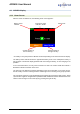
APR650 User Manual 3 Reader Hardware This chapter describes the APR650 hardware including all accessories. 3.1 Parts of the APR650 The dimensions of the APR650 are 190x98x40 millimeters and it has a weight of only 280 grams. It provides a good reading performance, a large 2.4 inch color TFT display, two status LEDs above the display, a speaker and a vibrating motor. The reader can be controlled with seven ergonomic keys below the display. In addition, there are 12 alphanumeric keys for entering data.
APR650 User Manual 3.2 Accessories The APR650 comes with a USB-A to Magnetic-Connector cable. The USB-A plug can be connected to any USB-port of a computer. Please note that the appropriate USB driver has to be installed first. When it is necessary to use a USB extension, this should only be high quality cable and it should not be longer than two meter. The maximum cable length for USB is five meter and this can already lead to problems in practice (slower charging or USB failures).
APR650 User Manual 3.3 Connecting the USB cable The APR650 uses a Magnetic-USB connector. Because the magnets are polarized, the connectors 'find' the correct orientation almost automatically. When the magnetic connector of the cable is moved towards the plug at the bottom of the reader (1), the magnets will attract each other in the correct orientation (2). In the wrong orientation, the magnets will repel each other.
APR650 User Manual 4.1 APR650 Display 4.1.1 Home Screen After the reader is switched on, the following home screen appears: Battery status indicator Connection status USB, BT, WLAN Current function of the left soft-key * Current time Current function of the right soft-key * * A 'Softkey' is a key that performs different functions depending on the associated screen display. The battery status indicator shows the approximate battery level. In this example the battery is fully charged.
APR650 User Manual 4.1.2 The status symbols at the top of the display There is a status bar in the first display line. Beside the time (on the right side) it provides information about the battery status and the different interfaces. The blue symbol is for WLAN and the orange one for Bluetooth. The color of the symbols depend on the current connection status. 4.1.2.1 Battery status The battery symbol on the left side indicates the approximate battery capacity.
APR650 User Manual 4.1.2.2 WLAN status Status Meaning WLAN is switched on but not connected to an Access Point. Connected to an Access Point and waiting for connection (listening). Connection is established (TCP or UDP – port is open) WLAN init: This symbol is displayed when the WLAN module is currently booting, being configured or a Firmware update is in progress. 4.1.2.
APR650 User Manual 4.2 The status LEDs above the display The APR650 has two status LEDs above the display. RGB The left LED is a multicolor type and is used for multiple purposes. When the display is switched off, it indicates the charging status of the battery. During the activation of the RFID engine it shows the reading status. Blue The LED on the right is blue and it is used for indicating the connection status with the display is switched off.
APR650 User Manual 4.3 Using the keyboard The APR650 has 19 keys in order to allow the easy and convenient operation of the reader. There is a directional pad with an ENTER key in the middle and there are two additional soft-keys below the display which change their function depending on the current action. For entering data fast and easy, the reader provides 12 alphanumeric keys.
APR650 User Manual Key Operation Enters the menu in the home screen. Moves up one menu level (‘Back’), other functions depend on current operation – the current function is always displayed on the left side in the last display line (above the key). When in the home screen, the configured ‘quick action’ will be executed. Exits the menu completely and moves back to the home screen. Other functions depending on the actual operation are shown in the display on the lower right side. Switches on the APR650.
APR650 User Manual The following examples show some more details on the keyboard usage: Beside the usage of the alphanumeric keys, it is possible to change the character of the currently selected position using the or button for simple text input fields. This is an extended text input field which starts a new group. The ↑ symbol in the status line indicates that the Caps Lock is activated (the [*] key was pressed). Hence all letters are directly entered as capitals.
APR650 User Manual 5 Operating states The APR650 has several operating states concerning display status and communication possibilities over USB. The following chart shows the different states. When the reader is switched on and it is connected via USB, it works in CDC-Mode. That means a virtual comport is created on the computer and it is possible to send commands to the device via a serial port connection.
APR650 User Manual 6 Reading Transponders 17/11/20 Page 17 of 54
APR650 User Manual 17/11/20 Page 18 of 54
APR650 User Manual After a tag has been read, the display will show the information as in the following screenshot: VID – Visual ID EID – Electronic ID Name of the current group, here: ‘group 9’ Number of records in the current group, here: ‘20’ Return to home screen Show more information If ‘Data’ was pressed, the screen on the left side is shown. It provides information about the EID, VID (if available), Date and Time of reading and the Alert text (if there is one for this tag).
APR650 User Manual 7 Barcode Reading The Barcode scanner can be started by pressing the button from the home screen. Scanning is active for a maximum of 10 seconds and an animation is shown on the display during this period. The scanner projects a blue aiming help which should be placed over the Barcode to scan it successfully. After the Barcode has been scanned, the device display shows the content of the code.
APR650 User Manual 8 Menu items In order to enter the APR650 menu, please press while in the home screen. In the lower left corner of the display you can also see the information that a press of the left soft key will force the device to enter the menu. This screenshot shows the highest menu level. It only contains the items ‘New Group’, ‘Data’, ‘Print’ and ‘Setup’. If another language than the default one has been selected, the menu items will look different.
APR650 User Manual 8.1 Menu structure The following table shows the menu structure of the APR650 including submenus and options. Options or actions are shown in italic and the default values for options are marked with ‘ * ’.
APR650 User Manual Main Menu Setup 1st sub menu Reader Settings 2nd submenu Volume & Vibrator 3rd submenu Set Volume Vibrator On/Off Display Set Date/Time Set Switch Off Time Set Display Colors Set language Interface Setup Setup Scale Setup Printer Bluetooth [set values manually] 60 min 30 min 20 min 10 min 5 min 3 min 2 min 90 sec 60 sec * 30 sec 20 sec 10 sec 5 sec Black * White [depends on uploaded languages] Set Scale Type [same as setup printer on the previous page] Set Bluetooth Mode Start
APR650 User Manual 8.2 New Group In the memory of the APR650, records are organized in groups. One group can contain up to 10.000 records maximum. A new record is created for every transponder which has been read. If you do not wish to create new records for duplicate reads, please enable the ‘Animal Counter’ – then duplicates will not be saved again within one group (see chapter 8.6.1.1) After ‘New Group’ was selected, the user will be prompted to insert a group name.
APR650 User Manual 8.3 Tasks This submenu is only visible if Task-Definitions have been uploaded. Such definitions are usually very much dependent on the application and thus Agrident cannot provide them. They are normally created by distributors who also offer Management-Software that supports Agrident mobile readers. If no Task-Definitions have been uploaded, this menu item will not be shown at all. Please contact your local distributor for further details about Task-Mode.
APR650 User Manual That is a Date-Field. The device suggests the current date but the user has the chance to edit it. … Increase number … Decrease number … Next field … Previous field … Confirm input When this field is shown, the APR650 will start scanning for a transponder after has been pressed. After a tag has been read successfully, the display will show the EID and ask for a confirmation. By pressing ‘OK’ (left soft key) the EID will be stored and the Task is continued.
APR650 User Manual 8.4 Data The ‘Data’ menu contains items for showing and deleting data. It is also possible to search an uploaded Database for a particular entry based on either the input of the VID or an EID (read transponder), but only if a Database has been uploaded. If this is not the case, these menu items are not shown. 8.4.1 Show Data When the item ‘Show Data’ was selected, the device will show a list of all groups which are present in the memory at the moment.
APR650 User Manual In order to show detailed information for a particular record, select an entry from the list and confirm with . The details of the record are shown on two pages. The first page shows the EID, the VID, date and time of reading and the alert string, if there is one assigned.
APR650 User Manual 8.4.2 Clear data It is possible to delete collected data on the APR650. There are different options for erasing data, also depending on the way they have been collected in. As already explained earlier in this manual, the standard records are saved in groups. These are the records which have been saved upon transponder reading started from the home screen.
APR650 User Manual 8.4.3 Memory Info This menu item shows information concerning the amount of collected data (how many records in how many groups), the number of entries in the currently uploaded Linklist or Database and how many Task definitions have been uploaded. It does not show how many records are present for each Task definition. Therefore please enter the Task menu, select a Task and use ‘Show Memory Info’ (8.3) 8.4.
APR650 User Manual The Database entry for the selected VID will be shown as usually. You may move to the previous / next (editable) field by using the / keys and switch between the different pages via or . The key allows to modify data, if the field is configured to be editable. Non-editable fields are only shown but can neither be selected nor modified. In this case the Database ‘creator’ did not want to allow editing this information. 8.4.
APR650 User Manual As soon as a tag has been read AND there is a match in the Database, the entry will be shown. You may move to the previous / next (editable) field by using the / keys and switch between the different pages via or . The key allows to modify data, if the field is configured to be editable. Non-editable fields are only shown but can neither be selected nor modified. In this case the Database ‘creator’ did not want to allow editing this information.
APR650 User Manual 8.5.2 Select Group This menu item allows to print a particular group instead of the last one or all groups. Select the group to be sent to the printer using the keys and confirm with . / If the Bluetooth connection has not been established yet, the APR650 will try to connect to the mobile printer now as explained in the previous chapter. If the connection to the printer is established, printing will start right away.
APR650 User Manual 8.5.5.2 Search BT Printer Before you can start printing via Bluetooth, the APR650 has to be paired with a printer. Therefore, the reader has to scan for available Bluetooth devices first. Once this menu item has been selected, the APR650 will start the scan. Depending on how many devices are present, the scan can take a while, but at least 10 seconds. If Bluetooth is switched off, the APR650 shows the corresponding error message.
APR650 User Manual 8.6 Setup The APR650 is very flexible concerning its configuration. Several settings can be adjusted directly in the device menu. However, it does not make sense to allow the modification of all possible reader settings on the device itself – this would make the menu structure far too complicated. Settings which cannot be modified on the APR650 itself, are software-adjustable. A possible software for altering all possible APR650 settings is AgriLink.
APR650 User Manual 8.6.1.2 Set Read Mode Per factory defaults, the APR650 is configured to ‘Single Read’. This means that RFID is activated until a transponder has been detected or the ‘Single Read Time’ (default = 10 seconds) has elapsed. The key has to be pressed in order to scan for tags again. The APR650 also allows to use the ‘Continuous Read’ mode. The RFID engine will not be deactivated after a tag has been read.
APR650 User Manual Select the correct output format via with . or and confirm The default output format is ‘Short ASCII 15’. This is sending the 3-digit country code directly followed by the 12-digit national ID (no space in between), terminated with . This format is quite common and also accepted by most weighing indicators on the market. There is a buffer of 20 IDs for sending the transponder number over Bluetooth or WLAN.
APR650 User Manual 8.6.1.5 Volume & Vibrator The APR650 provides a speaker and a vibrating handle for signalization in addition to the LEDs and the display. These can be configured in this menu. After selecting ‘Volume & Vibrator’, a new menu is shown. The first menu item allows to set the speaker volume, the second is used to activate the vibrating motor or to deactivate it. Select the desired volume by using the / keys.
APR650 User Manual 8.6.2.1 Set Date/Time DD … Date - Day MM … Date - Month YY … Date - Year hh … Time - Hour mm … Time - Minute / … Modify value in the current field / … Switch to previous / next field … Apply the new settings 8.6.2.2 Set Switch Off Time The ‘Switch Off Time’ determines after which period (of no action) the APR650 enters suspend mode. Any action, like a key press, will reset this timer. Please also see chapter 5 for further details.
APR650 User Manual 8.6.2.4 Set Language The default display language is always English. It is possible to upload up to 9 custom languages. If the language you want to use is not available, please contact your local distributor for further details. / … Select the desired language … Set the selected language 8.6.3 Interface Setup The Interface Setup contains settings for configuring the APR650s wireless interfaces (Bluetooth or WLAN). The scale and printer settings can be configured here as well. 8.6.3.
APR650 User Manual 8.6.3.2 Setup Printer The printer setup is the same as described in chapter 8.5.5, here is just another menu entry for configuring the same settings. 8.6.3.3 Bluetooth The APR650 always incorporates a Class1 Bluetooth module. The range is up to 80 meters in ‘line of sight’. Inside buildings or when any other obstacles are present, it will be less. Please note that the range also depends on the Bluetooth partner. If the other device is only Class2, the range is much lower.
APR650 User Manual The APR650 starts scanning for other Bluetooth devices in range. This can take quite a long time, also depending on how many devices are found, but at least 10 seconds. The discovered devices are listed after the scan, sorted according to their names. Sometimes it might be useful to see the BD-address of the found devices instead of the names. You may switch between both views by using the key.
APR650 User Manual The APR650 supports five different Bluetooth profiles: Serial Port Profile (SPP), IAP, Human Interface Device (HID) (+ HID smart) and Bluetooth Low Energy (BLE), where BLE is more or less another technology rather than a profile. SPP emulates a serial cable to provide a simple replacement for RS232 connections. Commands can be sent into both directions – it uses virtual serial ports. IAP The readers Bluetooth module is compliant with Apple’s iPod® Accessory Protocol.
APR650 User Manual The menu item ‘Bluetooth Info’ shows some Bluetooth hardware and firmware related information, the configured Bluetooth Mode & Profile and the connection status. Details concerning the color of the Bluetooth symbol depending on the connection status are explained in chapter 4.1.2.3.
APR650 User Manual 8.6.3.4 WLAN The WLAN function of the APR650 requires basic knowledge about networks and WLAN. It is recommended to let an IT specialist configure the required settings. The WLAN settings available on the device itself are only basic ones. Showing all possible settings would make the menu too complex, hence the advanced settings are only software configurable – e.g. via AgriLink.
APR650 User Manual Select the desired WLAN Mode using the keys and confirm with . / / / When the APR650 joined an Access Point or another device has joined the APR650 (in case the reader creates the Access Point), this does not mean that communication is possible already. In addition, a UDP or TCP connection must be opened, before data can be exchanged! Depending on the application, a UDP or TCP connection must be established and an appropriate port must be opened.
APR650 User Manual The menu item ‘Show WLAN Info’ displays hardware and firmware information of the WLAN module, a summary of the currently configured basic settings and the connection status. Information about the color of the WLAN symbol depending on the connection status are explained in chapter 4.1.2.2. The MAC Address is a unique 12-digit number which clearly identifies each network adapter worldwide. The SSID can be understood as the network name.
APR650 User Manual 8.6.4 Configuration After selecting ‘Configuration’, the menu shown on the left side will be displayed. 8.6.4.1 Set Factory Configuration ‘Set Factory Configuration’ puts all settings back to the factory default values. This might be useful if particular settings have been changed and the APR650 is not operating as intended anymore. Please note that this action cannot be undone. Settings different from the factory defaults have to be made again. …confirm reset … abort reset 8.6.
APR650 User Manual 8.6.5.1 Show Battery Info When fully charged, the battery info shows ‘100%’. Below the charging indication, the display shows rough estimates concerning the remaining operating time in standby mode (APR650 running but RFID engine is off), here 22 hours, and in continuous read mode, here 7 hours and 10 minutes. In this example the battery capacity is at 57 percent. The expected standby time is 12 hours and in continuous read mode there are 4 hours left.
APR650 User Manual 9 Battery precautions There are some important things to consider concerning the rechargeable battery pack. The allowed charge temperature is between 0°C to +45°C (32°F to 113°F). Discharging is allowed within the range of -20°C to +60°C (-4°F to 140°F) – this is the allowed operating temperature for the battery. Storage instructions: ▪ ▪ ▪ It shall be kept in shipping condition (70% discharge) or over than 70% discharge condition to storage for long period.
APR650 User Manual While charging: ▪ Be sure to follow the rules listed below while charging the battery. Failure to do so may cause the battery to become hot, explode, or ignite and cause serious injury. • When charging the battery, only use chargers supplied by Agrident. • Do not attach the batteries to a power supply plug or directly to a car's cigarette lighter. • Do not place the batteries in or near fire, or into direct sunlight.
APR650 User Manual 11 Warranty The manufacturer of the APR650 Reader Electronic will provide a warranty of 12 months from the day the device is shipped and subject to the following conditions: 1. Without submission of proof of purchase no warranty can be given. 2. In the event that defects are detected the manufacturer is entitled to choose between up to two attempts at repair or supplying a replacement device on one occasion.
APR650 User Manual 12.2 FCC and IC digital device limitations This device complies with Part 15 of the FCC rules. Operation is subject to the following two conditions: (1) This device may not cause harmful interference, and (2) this device must accept any interference received, including interference that may cause undesired operation. FCC Interference Statement (Part 15.
APR650 User Manual 13 Apple – Legal Notice iPod, iPhone, iPad are a trademark of Apple Inc., registered in the U.S. and other countries. “Made for iPhone” and “Made for iPad” mean that an electronic accessory has been designed to connect specifically to iPhone, or iPad, respectively, and has been certified by the developer to meet Apple performance standards. Apple is not responsible for the operation of this device or its compliance with safety and regulatory standards.