
User's Manual


29.05.2007 Page 10 of 59
ASR500 Reader Operation
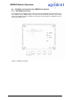
2.2.3 Electrical connection
The electrical connections for the power supply, the communication interfaces with the control-
ler (RS232 or RS485), and for connecting the antenna are made via terminal strips st3 and st4
on the printed circuit board.
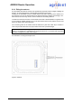
The corresponding cables are routed through the watertight screwed conduit cable entries. We
recommended that the interface cable be routed through the screwed conduit entry PG3, the
power supply cable through PG4 and the antenna cable through PG5.
Connections for synchronization should be routed through PG1 and PG2.
Improtant! Please close the unused screwed conduit entries with the enclosed blind plugs.
Please use only round cables, otherwise the protection class cannot be guaranteed.
To ensure the water tightness thoroughly tightens the screwed conduit entries.
ST1 Additional tuning capacitors
ST3 Antenna
ST4 Power supply, communication interface and synchronization
ST5,ST6 LED's D3,D6 and D9 and tuning switch
LED3,6,9 Tuning indicators power on and good read
J3,4,5 Communication interface selection
Their function is described in the next sections.
ST3
ST1
ST4
ST5
ST6
PG5 PG4
PG3
PG2 PG1
J1
J
5,3,4
3
LED 9
6