
User's Manual

05/11/13 Page 19 of 53
ASR550 Operational Manual
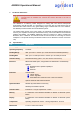
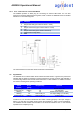
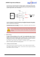
The two ends of the cable should have a termination resistor connected across the two wires.
Without termination resistors, reflections of fast driver edges can cause multiple data edges that
can cause data corruption. The value of each termination resistor should be equal to the cable
impedance (typically 120 ohms for twisted pairs).
The above drawing shows the RS485 schematic of the ASR550 including the fail-safe resistors.
These are necessary for biasing the lines to known voltages and nodes will not interpret the
noise from undriven lines as actual data.
The RS485 baud rate can be configured from 9600 to 115200 baud. Please ensure that all
nodes use the same and correct setting.
It is very important that each device on the bus uses a different network- or node
address. If several readers are using the same address, data collision might be
the result. You can change the reader’s node addresses via the Agrident Demo
Software.
4 ASR550 Settings
In order to allow the ASR550 to work in a wide range of applications, there are lots of
possibilities for changing the behavior of the reader, i.e. for altering several settings. Therefore
Agrident provides a PC Demo-Software which is available for free. You may also control the
reader with own software or change settings using the corresponding commands according to
the ASR550 protocol. Please see the ASR550 protocol description for details.
All the different reader settings will be explained in combination with the Agrident PC-Demo
Software for stationary readers in the following chapters.
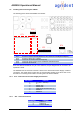
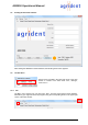
4.1 Installing the PC-Demo Software
Please start the setup file and follow the instructions in order to install the PC-Demo Software.
The Agrident PC-Demo Software is written in Visual Studio and thus requires the Microsoft
.NET Framework Version 2.0 or higher.
ASR550
µP
RS485-B
RS485-A
MAX483
120Ω
at the ends
of the bus
onl
y